
Electrical center with vertical power bus bar

a technology of electric center and bus bar, which is applied in the direction of electrical apparatus casing/cabinet/drawer, electrical apparatus connection, semiconductor/solid-state device details, etc., can solve the problem that the dissipation of heat generated by the bus bar can require special measures, and achieve the effect of reducing the foot print of the electrical center and improving the dissipation of hea

Inactive Publication Date: 2011-09-27
APTIV TECH LTD
View PDF63 Cites 25 Cited by
  • Summary
  • Abstract
  • Description
  • Claims
  • Application Information

AI Technical Summary

Benefits of technology

The invention is about an electrical center that has a power bus bar that reduces the size of the center and improves heat dissipation. The power bus bar is made of planar straps that are attached to a circuit board in a vertical position, which reduces the space requirements on the circuit board and increases heat transfer from the circuit board to the power bus bar and to the electrical center housing. The power bus bar acts as a heat sink for the circuit board and its components. The bus bar is made of a copper alloy material that has high conductivity both thermally and electrically. The technical effect of this invention is to improve the performance and reliability of the electrical center.

Problems solved by technology

However, in other instances, dissipation of the heat generated by the bus bars can require special measures.

Method used


Image

  • Electrical center with vertical power bus bar
  • Electrical center with vertical power bus bar
  • Electrical center with vertical power bus bar

Examples


Embodiment Construction

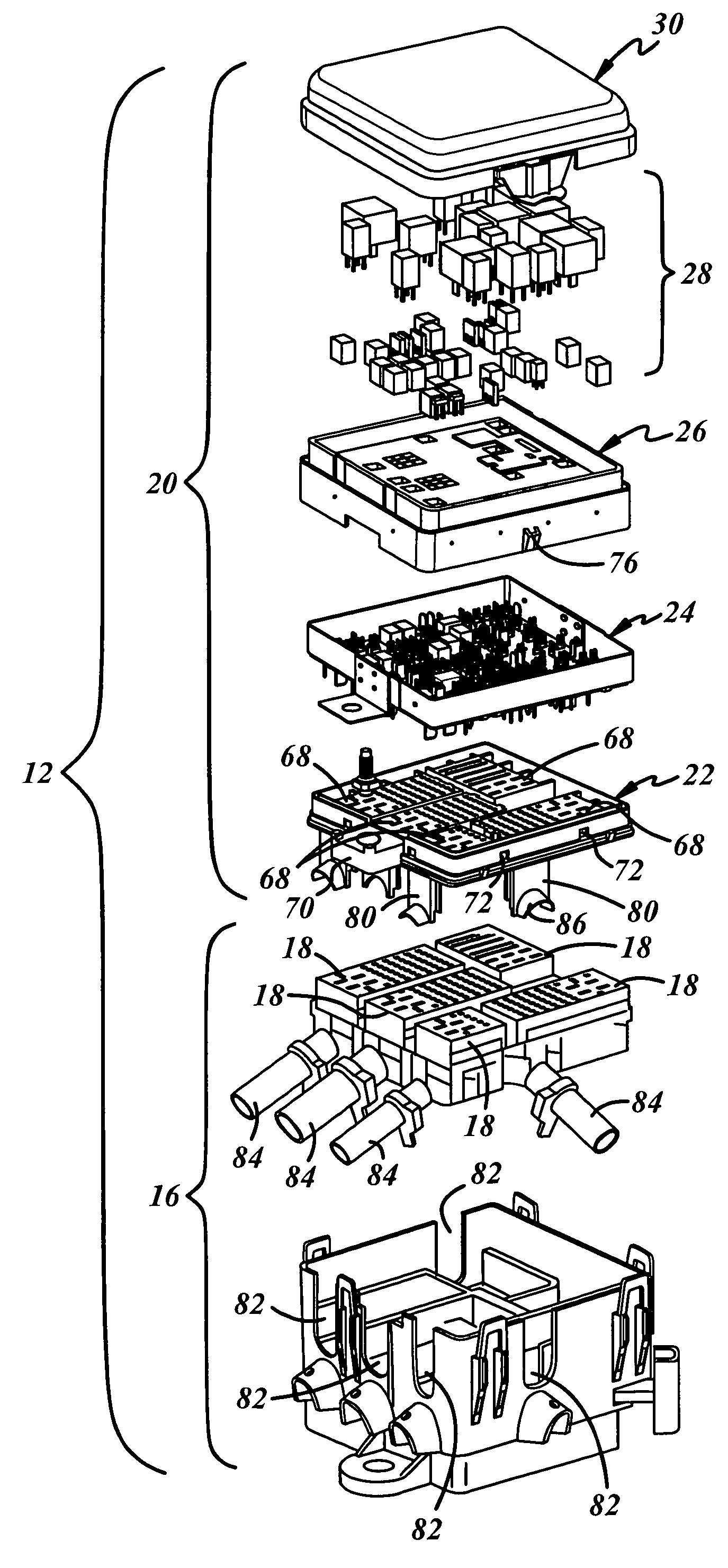
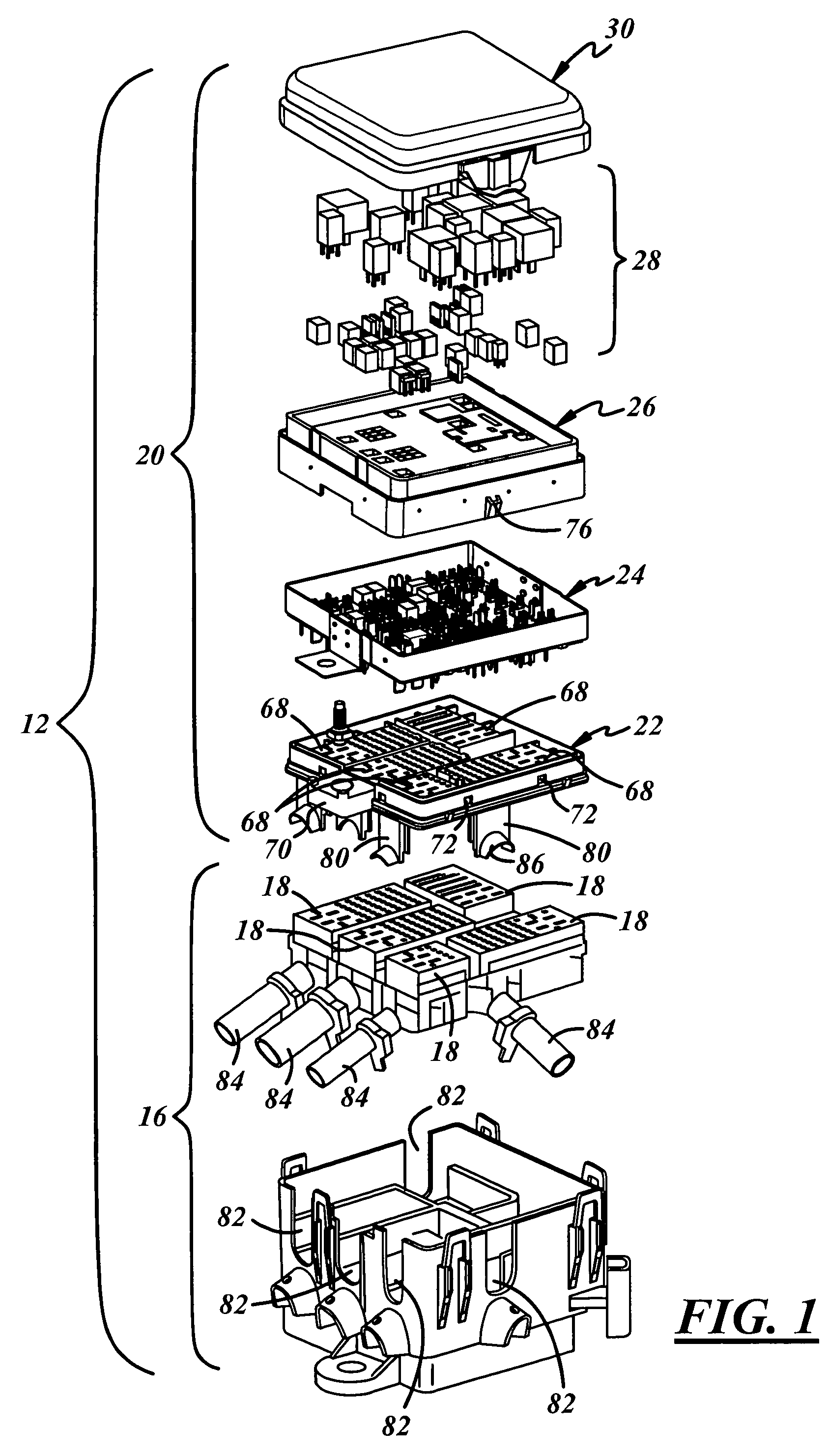
[0024]Referring now to FIG. 1, an electrical assembly 12 comprises a mounting bracket lift assembly 16 and an electrical center 20. The electrical center 20 is attached to the mounting bracket lift assembly 16 which has means for lifting wiring harness end connectors 18 or the like and plugging the end connectors 18 into electrical sockets of the electrical center 20. The mounting bracket lift assembly 16 is disclosed in detail in a companion patent application Ser. No. 12 / 228,447 being filed concurrently herewith and is hereby incorporated in this patent application by reference.

[0025]The electrical center 20 which may be used independently of the mounting bracket lift assembly 16, comprises a lower housing 22, a circuit board sub-assembly 24, an upper housing 26, electrical components 28 such as fuses and relays that plug into the upper housing 26 and a cover 30.

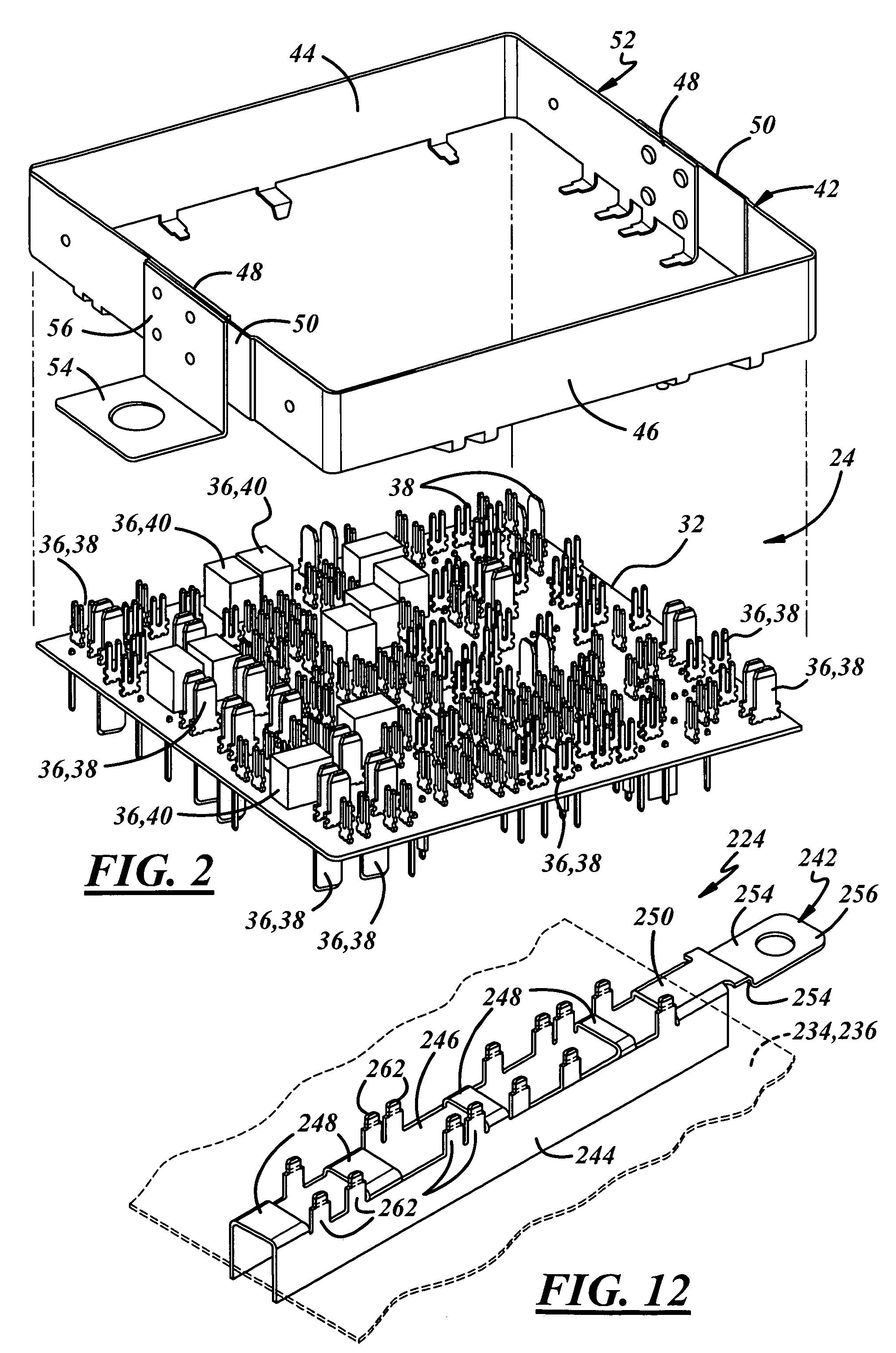
[0026]Referring now to FIGS. 2, 3, 4 and 5, the circuit board sub-assembly 24 includes a circuit board 32 having a subst...


PUM


Abstract

An electrical assembly comprises a mounting bracket lift assembly and an electrical center. The electrical center is attached to the mounting bracket lift assembly for plugging wiring harness end connectors into the electrical center. The electrical center comprises a lower housing, a circuit board sub-assembly, an upper housing, electrical components such as fuses and relays that plug into the upper housing and a cover. The circuit board sub-assembly includes a power bus bar that provides a power path for the various electrical circuits of the vehicle via the circuit components carried on the circuit board. Three power bus bars that are configured, oriented and located to reduce the foot print of the electrical center and / or to improve the dissipation of heat generated by the electrical center are disclosed.

Description

BACKGROUND OF THE INVENTION[0001]This invention relates to electrical center and more particularly to an electrical center that has a circuit board and a power bus bar.[0002]U.S. Pat. No. 5,032,752 issued to Gary C. Detter et al. Jun. 11, 1991 discloses an electrical distribution center for a vehicle electrical system that includes stacked circuit arrays of varying current capacity located between an upper housing and a lower housing each having terminal access holes for receiving terminals formed on pre-stamped metal circuit elements. The electrical terminals are selectively connected to either electrical or electronic devices carried on top of the upper housing or to wiring connectors connected to the outer surface of the lower housing. The pre-stamped metal circuit elements are removably mounted in recesses in a plurality of stacked electrical insulation boards supported within the lower housing.[0003]The electrical distribution center includes a power bus that includes an ear po...

Claims


Application Information

Patent Timeline
Patent Type & Authority Patents(United States)
IPC IPC(8): H05K5/00
CPCB60R16/0238H01R9/00H02G5/08
Inventor SENK, JOSEPH MATTHEWGLADD, JOSEPH HOWARDRONCONE, GINO M.KIRK, JOHN B.
Owner APTIV TECH LTD
Learn More