Scalable cladding mode stripper device

Active Publication Date: 2011-09-27
LUMENTUM OPERATIONS LLC
View PDF27 Cites 69 Cited by
  • Summary
  • Abstract
  • Description
  • Claims
  • Application Information

AI Technical Summary

Benefits of technology

In accordance with another aspect of the invention there is further provided a method of stripping a cladding mode of an optical fiber having a core and a first cladding, the method comprising:(a) disposing the optical fiber proximate to a reflective surface of a base for reflecting light of the cladding mode;(b) thermally coupling the optical fiber to the base for conducting heat away from the optical fiber;(c) disposing a first surface of a block of a transparent material on the reflective surface of the base and thermally coupling the first surface to the base for conducting heat away

Problems solved by technology

Having an external polymer coating is essential because without it, the optical fiber becomes very brittle; furthermore, for some fibers called “polymer-clad fibers”, the polymer layer functions as an outer optical cladding.
At high pump power levels, even a small fraction of stray light can heat the polymer to a temperature at which it can be damaged, causing catastrophic failure of the active fiber of the laser.
For instance, in fiber laser arrangements where the fiber is pumped at one end, and a catastrophic thermal failure occurs at the other end, the fiber can actually start

Method used


Image

  • Scalable cladding mode stripper device
  • Scalable cladding mode stripper device
  • Scalable cladding mode stripper device

Examples


Embodiment Construction

While the present teachings are described in conjunction with various embodiments and examples, it is not intended that the present teachings be limited to such embodiments. On the contrary, the present teachings encompass various alternatives, modifications and equivalents, as will be appreciated by those of skill in the art. In FIGS. 1 to 8, the like numerals refer to the like elements.

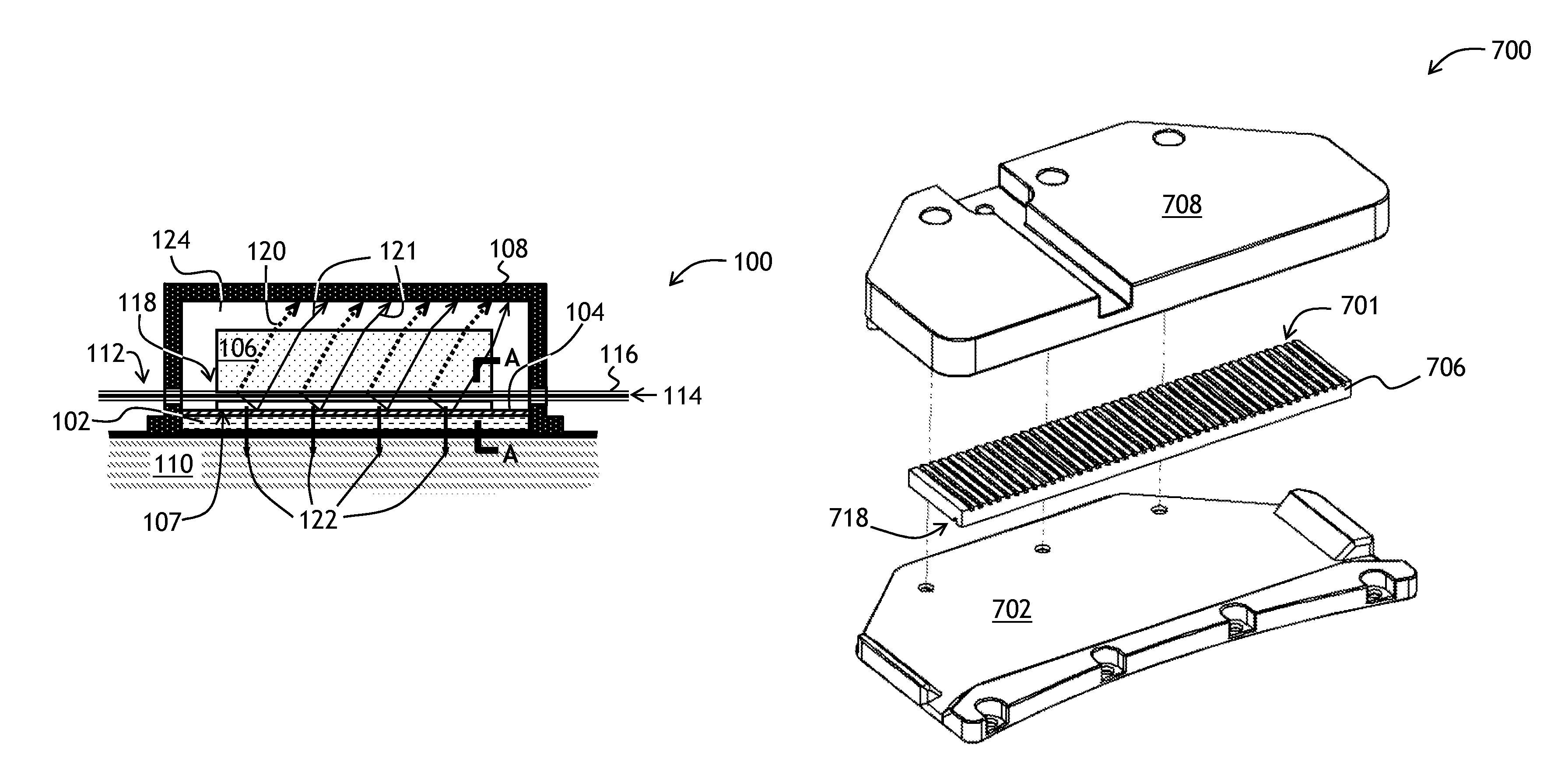
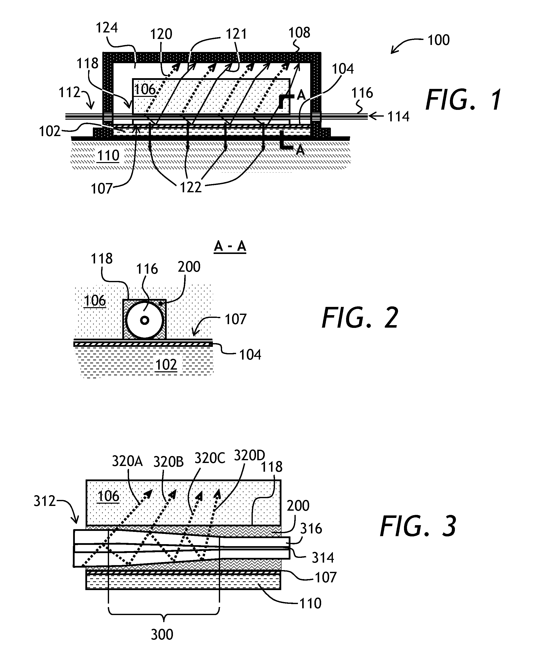
Referring to FIGS. 1 and 2, a cladding mode stripper device 100 of the invention is shown. The mode stripper device 100 has a base 102 having a reflective surface 104; a block 106 of a transparent material, disposed on the base 102 and thermally coupled to the base 102 for conducting heat away from the block 106; an optional opaque cover 108 thermally coupled to the base 102 for blocking light of the stripped cladding modes; and an optional heat sink 110 such as a thermoelectric (TEC) cooler, coupled to the base 102 for removing heat from the base 102. A bottom surface 107 of the block 106 is placed...


PUM


Abstract

A cladding mode stripper for stripping cladding modes from an optical fiber is disclosed. The cladding mode stripper includes a reflective base and a block of a transparent material disposed on the reflective base. The block of the transparent material has a groove in its bottom surface for the fiber. The fiber is thermally coupled to the base and optically coupled to the groove in the block, for example using an index matching gel. The cladding mode light is reflected from the reflective base and is absorbed in a cover enclosing the block. An additional thin block of transparent heat-conductive material can be placed between the fiber and the reflective base, to prevent the index matching gel from contacting the reflective surface of the base.

Description

TECHNICAL FIELDThe present invention relates to fiberoptic devices, and in particular to cladding mode strippers for stripping cladding modes of light from an optical fiber.BACKGROUND OF THE INVENTIONFiber lasers have significant advantages over traditional lasers, including stability of alignment, scalability, and high optical power of a nearly diffraction limited output beam. In a fiber laser, the gain medium is a length of an optical fiber, the core of which is doped with an active lasing material, typically ions of a rare earth element, such as erbium or ytterbium or both. The lasing material is usually pumped using an emission of a diode laser, or an array of diode lasers. The advent of double clad active optical fibers having inner and outer claddings, in which the pump light is coupled to the inner cladding to be absorbed at the doped fiber core along the fiber length, allowed a considerable increase in overall output power of a fiber laser, while preserving the brightness an...

Claims


Application Information

Patent Timeline
IPC IPC(8): G02B6/26
CPCG02B6/2852G02B5/003G02B6/14
Inventor KLINER, DAHVTUCKER, DEREK A.LUGO, JUAN
Owner LUMENTUM OPERATIONS LLC
Why Eureka
Try Eureka