
Ultra high-power continuous wave planar waveguide amplifiers and lasers

a laser and amplifier technology, applied in the field of ultrahigh-power continuous wave planar waveguide lasers and amplifiers, can solve the problems of limiting power scalability, relatively non-flexible, and generally very short planar waveguides, and achieve the effect of avoiding bend losses

Inactive Publication Date: 2005-06-07
BOSTON LASER
View PDF11 Cites 56 Cited by
  • Summary
  • Abstract
  • Description
  • Claims
  • Application Information

AI Technical Summary

Benefits of technology

"This patent describes a new type of laser or amplifier that can generate very powerful optical beams. These lasers and amplifiers use special techniques to guide the light in a very precise way. The lasers are made using rare-earth materials or transition metals, which are doped into a planar core region. The planar core is surrounded by regions of different refractive index to achieve the desired waveguiding properties. The lasers can be coiled along a short axis to reduce bending losses. The patent also describes a method for manufacturing these lasers using conventional techniques. The technical effects of this patent are the creation of new lasers and amplifiers that can generate high-quality optical beams with ultra-high power."

Problems solved by technology

However, such planar waveguides. are generally very short (i.e., of the order of a few cm) and relatively non-flexible.
Therefore, very high pump power absorption is required in these structures, thereby limiting power scalability.
However, because of the susceptibility of optical fibers to backward stimulated Brillouin scattering, the generation of single-frequency signals is very ineffective in optical fibers and, to date, the maximum achieved power level is limited to only about 25 W. The wide-spread use of fiber amplifiers or lasers in high power single-frequency amplification and generation thus requires an increase of the fundamental Brillouin threshold.
However, the use of large core multimode fibers is limited by the increased susceptibility of large mode fibers to mode-coupling, which results in a reduced mode-quality.
However, the use of large core single-mode fibers is limited by their increased susceptibility to bending losses.
However, severe bending of optical fibers can have negative implications on fiber life-time, especially for large diameter fibers and thus fiber bending cannot be considered for the construction of large-mode, ultra high-power fiber lasers.
However, multi-core fibers are difficult to manufacture and moreover, mode-coupling between various allowed supermodes results in a degradation in mode quality and severely limits the scalability of this approach.
However, circular as well as ribbon multi-core fibers are susceptible to modecoupling, severely limiting the maximum achievable mode size.
To date a mode size exceeding 50 μm has not been achieved in either of these approaches.

Method used


Image

  • Ultra high-power continuous wave planar waveguide amplifiers and lasers
  • Ultra high-power continuous wave planar waveguide amplifiers and lasers
  • Ultra high-power continuous wave planar waveguide amplifiers and lasers

Examples


Embodiment Construction

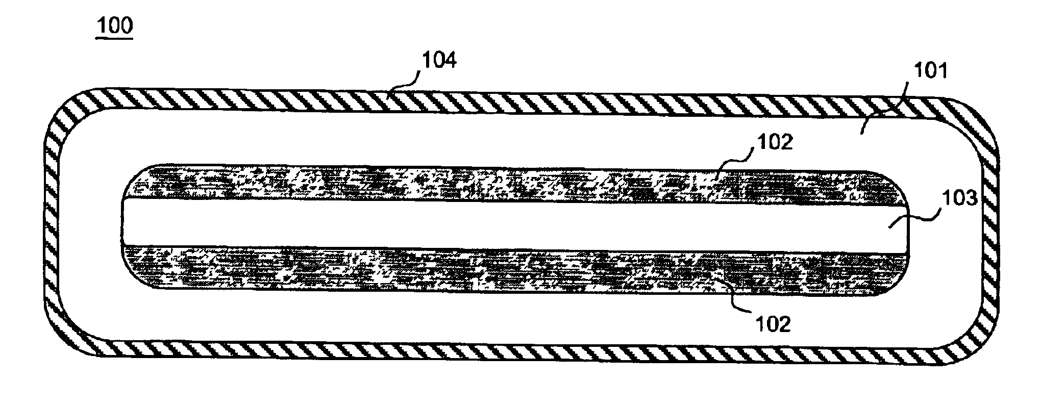
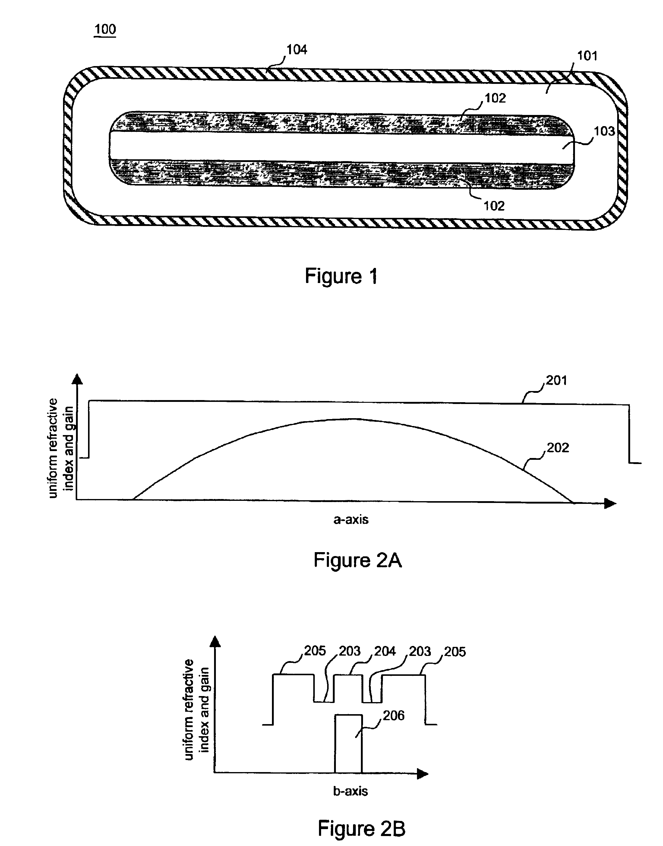
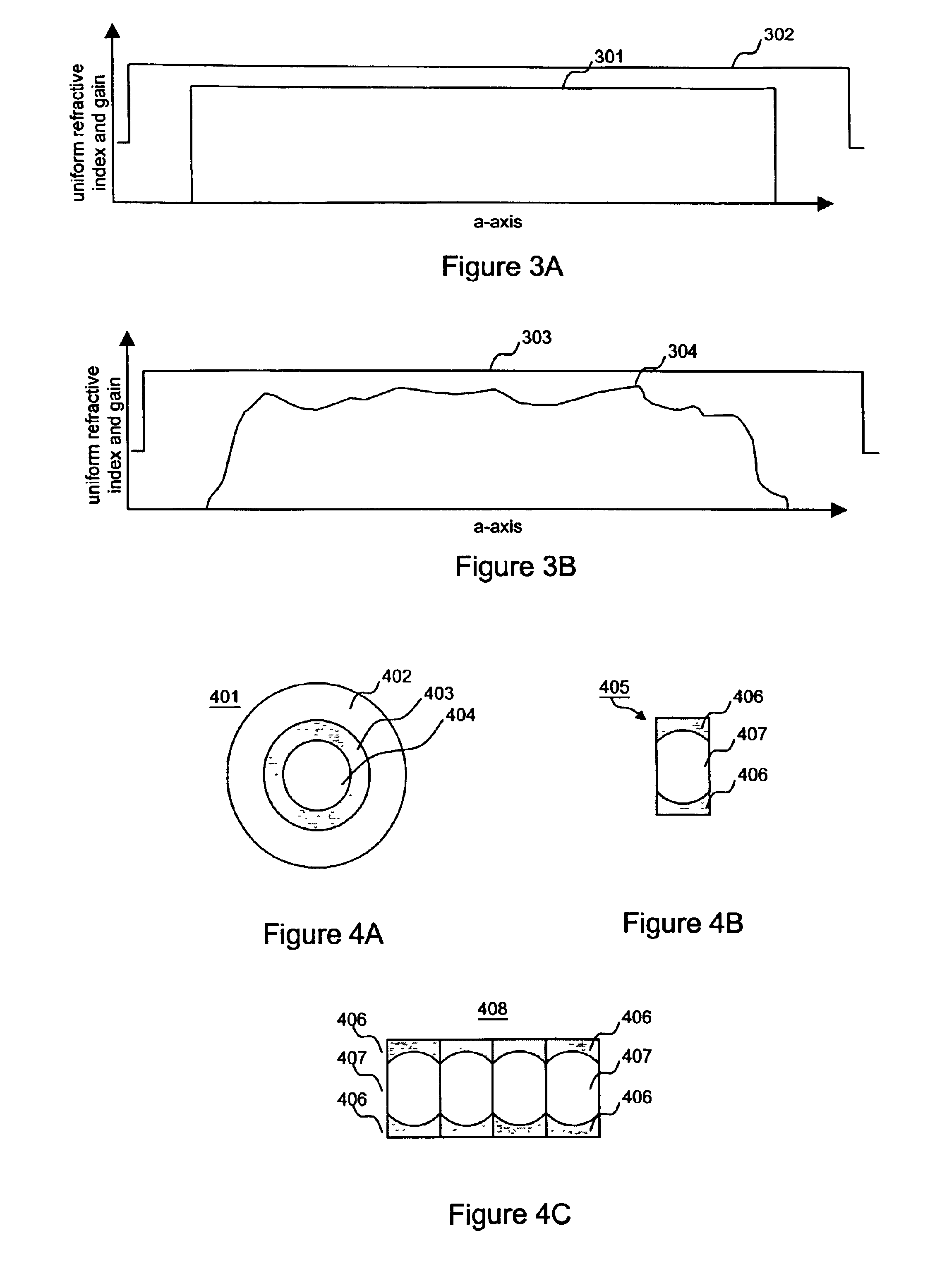
[0024]The cross section of a planar waveguide 100 according to an embodiment of this invention is shown in FIG. 1. In the following we refer to a planar waveguide simply as ‘planar’. The planar comprises a silica cladding 101, a depressed index cladding region 102, an index-matched parabolic gain profile rare-earth-doped planar core region 103 and a low refractive index outer coating (or cladding) 104. Though rare-earth-doping of the core region is preferred to produce a gain profile, doping with transition metals can alternatively be employed to produce a core region with a gain profile. For convenience we refer to the long planar axis as the a-axis and the short planar axis as the b-axis. Generally, rare-earth materials such as Nd, Yb, Er, Er / Yb, Tm, Ho or Pr or transition metals such as Cr or Ti are used as dopants to obtain gain in planar core region 103.

[0025]Low refractive index outer coating 104 is based on a Fluor-containing polymer and can also comprise Teflon, which provid...


PUM

PropertyMeasurementUnit
poweraaaaaaaaaa
powersaaaaaaaaaa
mode sizeaaaaaaaaaa

Abstract

Double clad large mode area planar lasers or amplifiers comprising rare-earth or transition metal doped planar core regions are used to generate near-diffraction-limited optical beams of ultra-high power. The amplified light is guided in the core using different guiding mechanisms in two orthogonal axes inside the core. Waveguiding along a first long core axis is obtained substantially by gain-guiding or thermal lensing. Waveguiding along a second short core axis is obtained by index guiding. This is accomplished by surrounding the planar core region with regions of different refractive index. The long sides of the planar core region are surrounded with a depressed refractive index cladding region. The short sides of the planar core region are surrounded with a cladding region substantially index-matched to the core region. The whole structure is surrounded by an outer cladding region with a low refractive index to enable cladding pumping of the planar waveguide with high-power diode lasers. The rare-earth or transition metal doping level inside the planar core can be constant and can also vary substantially without negatively affecting the waveguiding properties. To avoid bend losses along the long axis of the planar waveguide, the planar core region and the planar waveguide are aligned parallel to each other and the planar waveguide is coiled with the long side of the planar waveguide mounted to a drum. The drum can also be used as a heat sink. A planar waveguide comprising a planar core region can be manufactured using conventional fiber fabrication methods.

Description

FIELD OF THE INVENTION[0001]This invention relates to ultra-high power continuous wave planar waveguide lasers and amplifiers and more particularly a large mode area flexible planar waveguide.DESCRIPTION OF THE PRIOR ART[0002]Planar waveguide lasers are currently well established as efficient means of generating high optical power levels from compact packages. Recently, power levels up to 16 W have been obtained from a large mode area planar waveguide laser (W. S. Pelouch, ‘Self-Imaging in Waveguide Lasers and Amplifiers’, Opt. Soc. Am. Conf. On Advanced Solid State Lasers, Quebec City, (2002), paper MA2-1). However, such planar waveguides. are generally very short (i.e., of the order of a few cm) and relatively non-flexible. Therefore, very high pump power absorption is required in these structures, thereby limiting power scalability.[0003]Alternatively, over the last several years fiber lasers have been established as one of the most efficient means for converting electrical to op...

Claims


Application Information

Patent Timeline
Patent Type & Authority Patents(United States)
IPC IPC(8): G02B6/12C03B19/14C03B23/20C03B37/012G02B6/02G02B6/036G02B6/42
CPCC03B19/1469C03B23/20C03B37/01228G02B6/03644G02B6/02057H01S3/06729G02B6/4202G02B6/4204H01S3/0672
Inventor FERMANN, MARTIN E.
Owner BOSTON LASER
Learn More