
Multistage optical amplifier having a fiber-based amplifier stage and a planar waveguide-based amplifier stage

a technology of amplifier stage and fiber-based amplifier, which is applied in the direction of fiber transmission, lasers, transmission, etc., can solve the problems of reducing the overall gain supplied by the amplifier, preventing the full utilization of erbium-doped fiber amplifiers, and tight design and fabrication tolerances

Inactive Publication Date: 2005-03-08
AVAGO TECH WIRELESS IP SINGAPORE PTE
View PDF9 Cites 5 Cited by
  • Summary
  • Abstract
  • Description
  • Claims
  • Application Information

AI Technical Summary

Benefits of technology

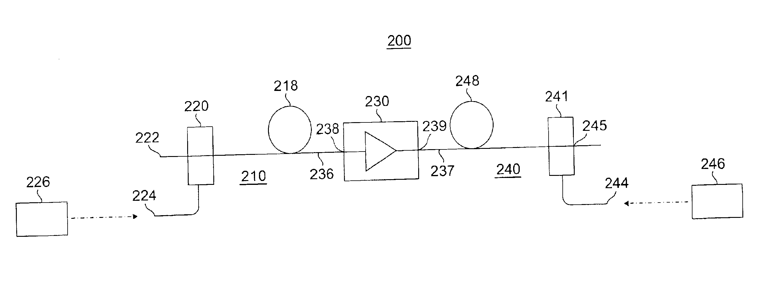
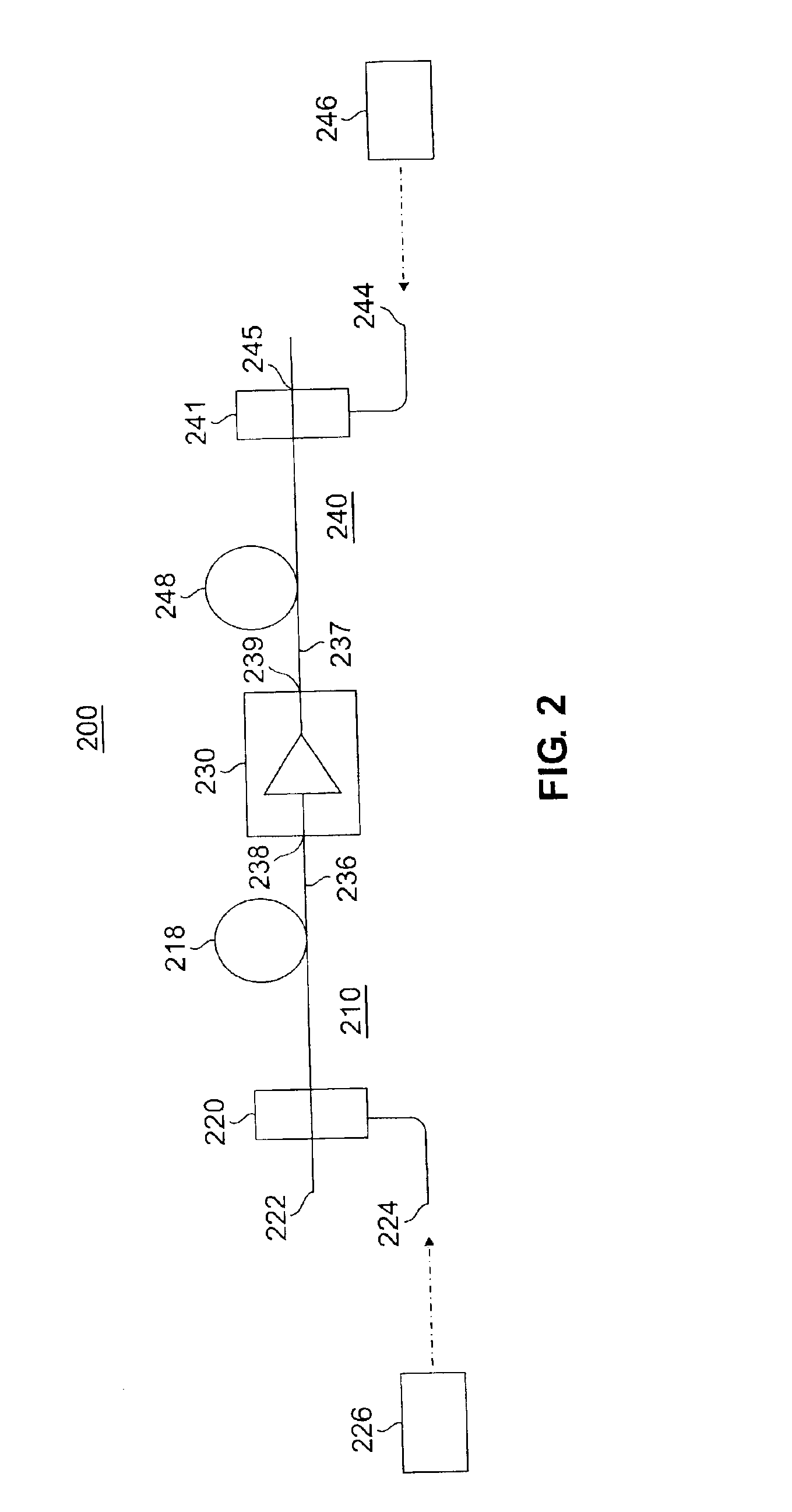
"The present invention provides a multistage optical amplifier that includes a fiber amplifier stage and a planar waveguide amplifier stage. The fiber amplifier stage has an active optical fiber for imparting gain to an optical signal propagating therethrough and a coupler supplying pump energy to the optical fiber. The planar waveguide amplifier stage has an active planar waveguide for imparting gain to an optical signal propagating therethrough and at least one waveguide coupler for coupling pump power to the active planar waveguide. The fiber amplifier stage is connected to the planar waveguide amplifier stage through an optical connection. The technical effects of this invention include improved optical signal amplification and reduced signal loss during optical signal transmission."

Problems solved by technology

It has been found, however, that this arrangement not only leads to rather stringent design and fabrication tolerances for a high-performance optical amplifier, but it prevents the full exploitation of erbium-doped fiber amplifiers.
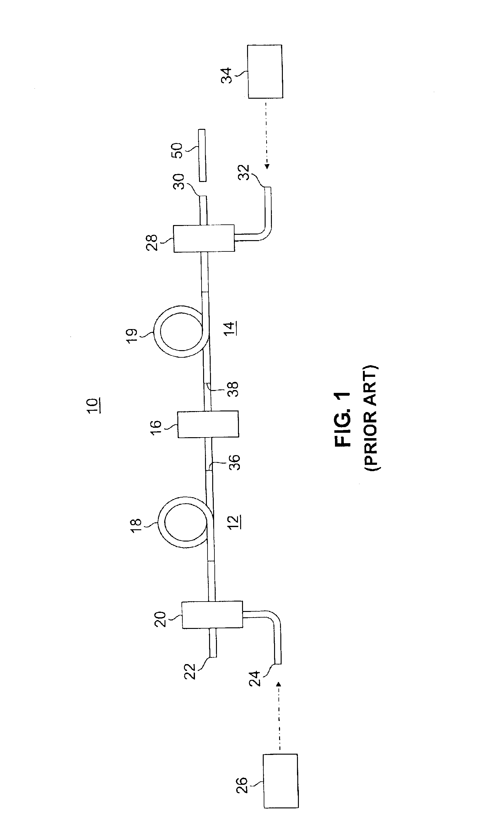
One problem with an optical amplifier that comprises multistage EDFAs is that because they employ a multitude of components they can be difficult to assemble and require a large number of splices that contribute to loss that reduces the overall gain supplied by the amplifier.
Moreover, as the number of stages increase, the amount of space the amplifier occupies can be come unduly large.

Method used


Image

  • Multistage optical amplifier having a fiber-based amplifier stage and a planar waveguide-based amplifier stage
  • Multistage optical amplifier having a fiber-based amplifier stage and a planar waveguide-based amplifier stage
  • Multistage optical amplifier having a fiber-based amplifier stage and a planar waveguide-based amplifier stage

Examples


Embodiment Construction

The present inventor has recognized that a multistage optical amplifier can be formed from one or more stages of an EDFA (or other rare-earth doped fiber amplifier) that is combined with one or more stages of a rare-earth doped optical amplifier that is not an EDFA, but rather which is a planar waveguide optical amplifier. In contrast to fiber amplifiers, which are optical glass fibers having cores doped with the optically active element, waveguide amplifiers are planar waveguides fabricated on suitable substrates such as silicon. The planar waveguide amplifiers include cores doped with an optically active element such as a rare-earth element.

Fiber amplifiers have traditionally been favored over waveguide amplifiers in most applications because waveguide amplifiers are typically much shorter, requiring a correspondingly higher level of doping to achieve the necessary gain of fiber amplifiers. Higher levels of doping adversely affect the efficiency of the amplifier. However, waveguid...


PUM


Abstract

A multistage optical amplifier includes a fiber amplifier stage having an active optical fiber for imparting gain to an optical signal propagating therethrough and a coupler supplying pump energy to the optical fiber. A planar waveguide amplifier stage is optically coupled to the fiber amplifier stage. The waveguide amplifier including a substrate, an active planar waveguide formed on the substrate for imparting gain to an optical signal propagating therethrough, and at least one waveguide coupler formed on the substrate for coupling pump power to the active planar waveguide.

Description

FIELD OF THE INVENTIONThe present invention relates generally to optical amplifiers for lightwave communication systems and, more particularly, to a multistage optical amplifier that include a fiber-based amplifier stage and a planar waveguide-based amplifier stage.BACKGROUND OF THE INVENTIONOptical amplifiers such as erbium-doped fiber amplifiers (EDFAs) have been used as power amplifiers, repeaters and preamplifiers in lightwave systems and have been responsible for significant improvement in the performance of long-distance transmission systems, networks, CATV distribution and the like. A number of types of optical amplifiers have been developed. One class of optical amplifiers is rare-earth doped optical amplifiers, which use rare-earth ions as the active element. The ions are doped in the fiber core and pumped optically to provide gain. The silica core serves as the host medium for the ions. While many different rare-earth ions such as neodymium, praseodymium, ytterbium etc. ca...

Claims


Application Information

Patent Timeline
Patent Type & Authority Patents(United States)
IPC IPC(8): H01S3/06H01S3/067H01S3/16H01S3/094H01S3/063
CPCH01S3/06758H01S3/0632H01S3/0637H01S3/1608H01S3/094096
Inventor FROLOV, SERGEYSHMULOVICH, JOSEPHBRUCE, ALLAN JAMESSHEN, TEK-MING
Owner AVAGO TECH WIRELESS IP SINGAPORE PTE
Learn More