Pressure equalizing device, receptacle and method

a technology of pressure equalizing device and receptacle, which is applied in the direction of fluid pressure control, liquid dispensing, bottling operations, etc., can solve the problems of high installation, maintenance and repair costs, and achieve the effect of reducing the risk of gas-borne particles, reducing the risk of substances contaminating breathable air, and high efficiency

Active Publication Date: 2011-10-04
CARMEL PHARMA
View PDF236 Cites 68 Cited by
  • Summary
  • Abstract
  • Description
  • Claims
  • Application Information

AI Technical Summary

Benefits of technology

[0007]The pressure equalizing device equalizes pressure in the fluid container and the receptacle by allowing filtered fluid to flow into or out of the receptacle (depending on whether the pressure is temporarily greater in the fluid container or the receptacle). The pressure equalizing device thereby provides a simple, closed system that allows for safe and reliable injection or withdrawal of substances, such as toxic drugs, into or out of a receptacle while at least minimizing, or eliminating the risk of the substances contaminating breathable air.
[0011]According to another embodiment of the invention the fluid inlet is arranged to be in communication with ambient, i.e. non-sterilized air. Since ambient air can be cleaned on site using a sterilizing or ascepticizing filter in the pressure equalizing device, neither a sterile environment, nor extra equipment, nor a supply of clean air is necessary to fill the fluid container with cleaned air. The pressure equalizing device according to the present invention may therefore be filled or replenished with cleaned fluid almost anywhere, in a simple manner and at low cost.

Problems solved by technology

However, such facilities require a lot of space, they are non-portable and can be expensive to install, maintain and repair.

Method used


Image

  • Pressure equalizing device, receptacle and method
  • Pressure equalizing device, receptacle and method
  • Pressure equalizing device, receptacle and method

Examples


second embodiment

[0036]FIGS. 4 and 5 show part of a pressure equalizing device 10 according to the invention. The pressure equalizing device comprises connecting means 22 for attachment to a receptacle and connecting means 23, namely a bayonet coupling, for attachment to an injector, such as a syringe, and a gas container 16 comprising a plastic parabola 16a and a flexible portion (not shown) that is attached to the plastic parabola 16a. A filter may be placed in the filter-receiving means 30 to filter gas entering the gas container 16 via the air inlet 20 (that is hidden behind the filter-receiving means 30 in FIGS. 4 and 5).

[0037]The filter-receiving means 30 are either integrally formed with the plastic parabola 16a of the gas container 16, by a blow moulding or vacuum forming process for example, or are attached to the inner surface of the plastic parabola 16a, by a continuous welding process, such as ultrasound welding, for example. Ultrasound is used to generate internal friction in the plasti...

third embodiment

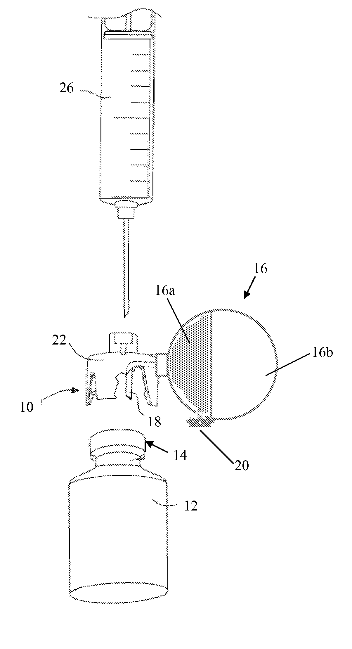
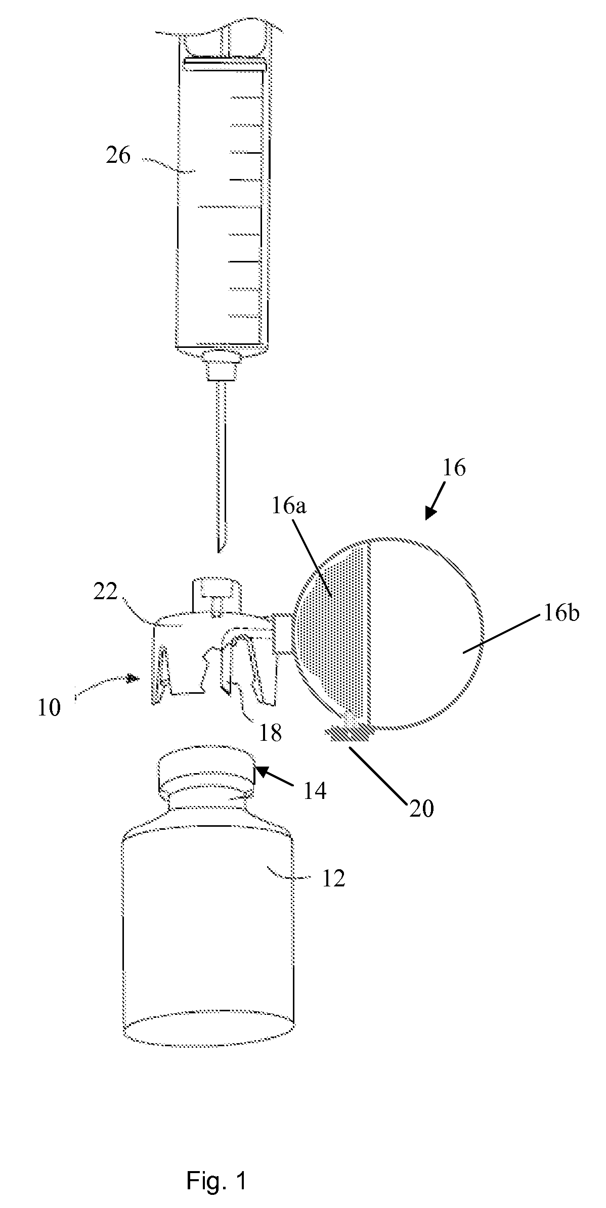
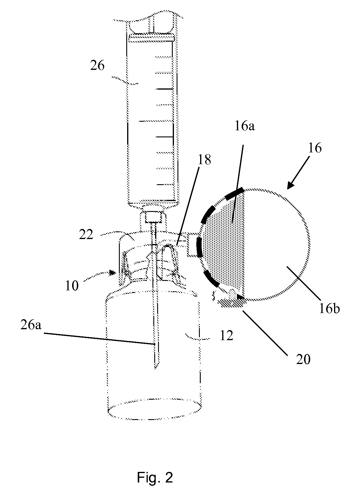
[0039]FIG. 6 shows an exploded view of part of a pressure equalizing device 10 according to the invention. The gas container 16 comprises a parabola 16a and a flexible portion 16b comprising a thin transparent film. The gas container 16 comprises an air inlet 20 and a one-way valve 28 is located in the air inlet 20. FIG. 7 shows the pressure equalizing device 10 of FIG. 6 when in use. Gas flows into the gas container 16 in the direction of the arrows in FIG. 7, namely through the openings in part 24 of the gas container 16, through a filter 34 into the air inlet 20 via radial channels and past the one-way valve 28 into the interior of the gas container 16. The part 24 comprising the openings in the illustrated embodiment may be arranged to be removable from the gas container 16 or it may be fixedly attached thereto, by means of adhesion or welding for example. FIG. 7 shows that filter-receiving means 30 may be placed at the mouth of the flow channel 18 that provides gas communicatio...

fourth embodiment

[0040]FIGS. 8-10 show part of a pressure equalizing device 10 according to the invention. The pressure equalizing device 10 comprises a gas container comprising a parabola 16a and means 22 for connecting the pressure equalizing device 10 to an receptor. The gas container 16 may be detachable from the connecting means 22. The gas container 16 is for example attached to the connecting means 22 by means of a bayonet coupling or any other releasable coupling means. Filter-receiving means 30 are placed in between the gas container 16 and the connecting means 22.


PUM

PropertyMeasurementUnit
sizeaaaaaaaaaa
volumeaaaaaaaaaa
volumeaaaaaaaaaa

Abstract

Pressure equalizing device comprising a fluid container for attachment to a receptacle such as a vial to permit pressure equalization between the fluid container and the receptacle. The pressure equalizing device comprises a flow channel that is arranged to provide fluid communication into or out of the fluid container when the pressure equalizing device is attached to the receptacle. The pressure equalizing device also comprises a fluid inlet that contains a one-way valve that permits fluid to flow into the fluid container via said fluid inlet and that prevents fluid from flowing out of the fluid container via said fluid inlet and filter-receiving means that are arranged to permit fluid flowing into or out of the fluid container to be filtered when the filter-receiving means comprises a filter.

Description

TECHNICAL FIELD[0001]The present invention concerns a pressure equalizing device comprising a fluid container, i.e. liquid and / or gas container, for attachment to a receptacle, such as a vial, to permit pressure equalization between the fluid container and the receptacle. The present invention also concerns a receptacle comprising such a pressure equalizing device.BACKGROUND OF THE INVENTION[0002]When preparing and administering drugs care has be taken to minimize, or preferably eliminate the risk of exposing people, such as medical and pharmacological personnel, to toxic substances. Safety boxes, cabinets or isolators are often used to prepare drugs to reduce the risk of toxic substances leaking into breathable air. However, such facilities require a lot of space, they are non-portable and can be expensive to install, maintain and repair.[0003]Some drugs must be dissolved or diluted before they are administered, which involves transferring a solvent from one container to a sealed v...

Claims


Application Information

Patent Timeline
Patent Type & Authority Patents(United States)
IPC IPC(8): A61M5/00
CPCA61J1/2096A61J2001/201A61J2001/2075A61J1/201A61J1/2075
Inventor HELMERSON, ELISABET
Owner CARMEL PHARMA
Why Eureka
Try Eureka