Wireless magnetic resonance imaging upconversion stage with a paramagnetic amplifier and delay line converting RF signals to microwave signals

a technology of paramagnetic amplifier and delay line, which is applied in the direction of wave based measurement system, instruments, and reradiation, etc., can solve the problems of increasing the downtime between scans, adding cost and inconvenience to the structure,

Inactive Publication Date: 2011-10-04
SIEMENS HEALTHCARE GMBH
View PDF29 Cites 4 Cited by
  • Summary
  • Abstract
  • Description
  • Claims
  • Application Information

AI Technical Summary

Problems solved by technology

These add cost and inconvenience to the structure.
In use, the requirement to connect the cables and sterilize them between scanning one patient and the next leads to increased down-time between scans.
However, a wireless solution permitting the cables to be eliminated still needs to substantially satisfy all the requirements of the existing system, particularly with regard to noise.

Method used


Image

  • Wireless magnetic resonance imaging upconversion stage with a paramagnetic amplifier and delay line converting RF signals to microwave signals
  • Wireless magnetic resonance imaging upconversion stage with a paramagnetic amplifier and delay line converting RF signals to microwave signals
  • Wireless magnetic resonance imaging upconversion stage with a paramagnetic amplifier and delay line converting RF signals to microwave signals

Examples


Embodiment Construction

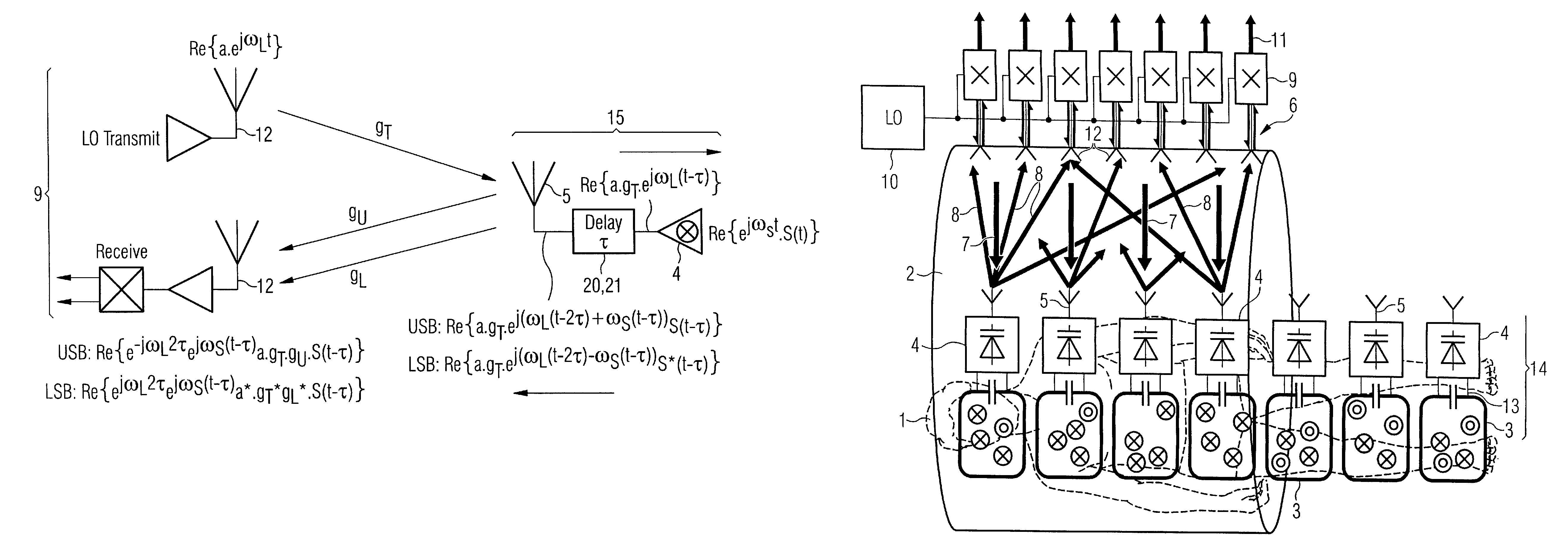
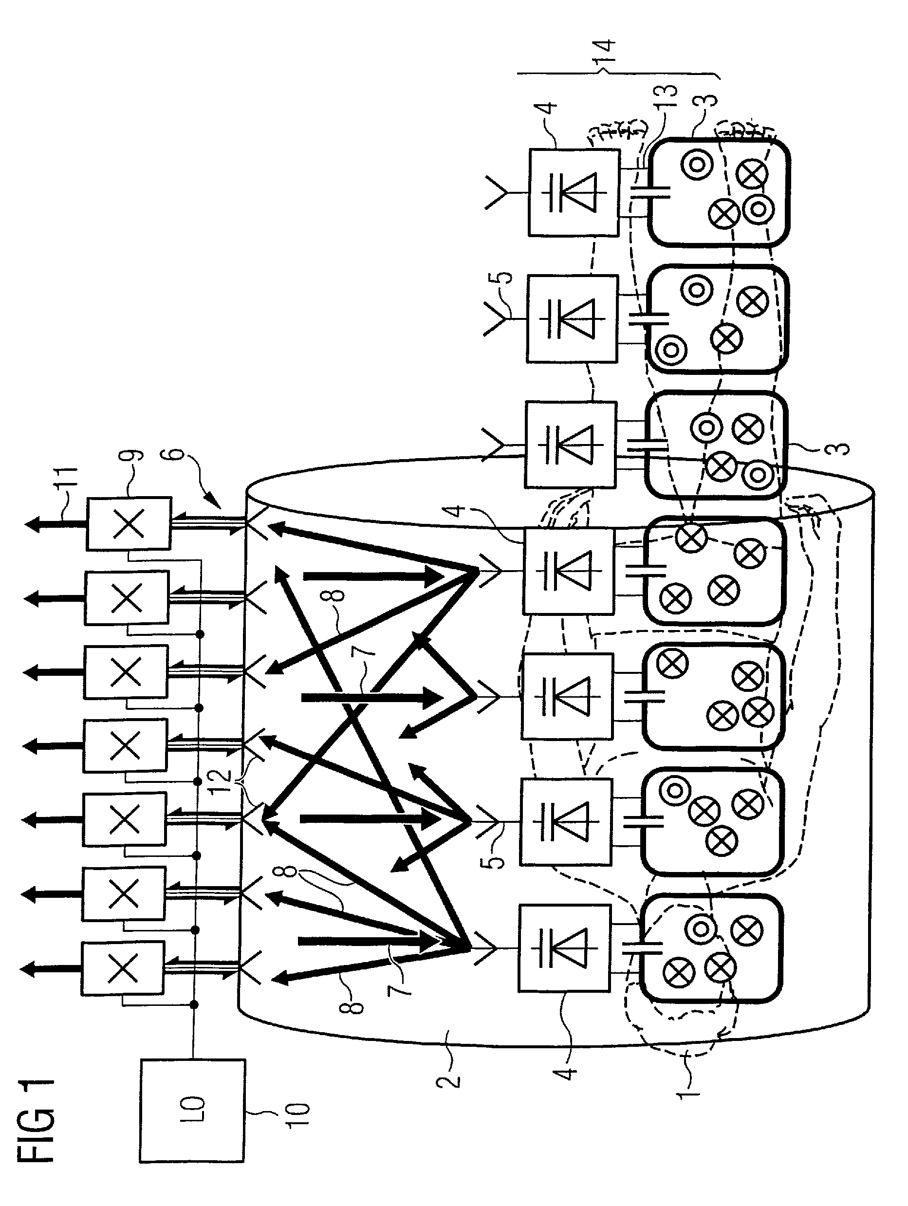
[0019]The wireless concept to which the features of the present invention apply is based on upconversion of the RF (Larmor) frequency signals to microwave frequencies and transmission from local coils located in the patient blanket to microwave antennas located on the bore of the scanner. The Larmor frequency ω0 is dependent upon the gyromagnetic ratio y and the magnetic field strength B0.The combination of transmit and receive antennas on the patient and bore respectively constitutes a MIMO (Multiple Input / Multiple Output) system that allows individual signals from the patient antennas to be resolved. A wireless system greatly enhances the utility of MRI scanners by removing the requirement for cable connections to patient coils and gives rise to significant work flow benefits from eliminating the need to sterilise, connect and disconnect the cables. With substantially no reduction of bore size, an increased coil density above the current norms may be achieved, as well as improving...


PUM


Abstract

An upconversion stage for a wireless magnetic resonance imaging system local coil array has a number of upconversion circuits. Each upconversion circuit includes a parametric amplifier, an antenna and a delay line between the amplifier and the antenna. The path length of the delay line in one upconversion circuit differs from the path length of the delay line in an adjacent upconversion circuit by a predetermined amount.

Description

BACKGROUND OF THE INVENTION[0001]1. Related Applications[0002]This application is related to the subject matter of the following applications filed simultaneously herewith, designated with Ser. Nos. 12 / 612,831 and 12 / 612,842 and 12 / 612,856 and 12 / 613,004 and 12 / 613,082.[0003]2. Field of the Invention[0004]The present invention relates to an upconversion stage for a local coil array, in particular a local coil array of the type providing phase scrambling for improved resolution in wireless coils magnetic resonance imaging (MRI).[0005]3. Description of the Prior Art[0006]MRI scanners use a combination of a strong constant magnetic field (B0) from a superconducting magnet which is modified by gradient fields generated by gradient coils, together with a rotating magnetic field (B1) from a radio frequency (RF) antenna to excite nuclear magnetic resonances in the body that generate short term RF signals that are received to build up a tomographic image.[0007]All current-generation MRI sca...

Claims


Application Information

Patent Timeline
Patent Type & Authority Patents(United States)
IPC IPC(8): G01V3/00G06K9/00
CPCG01R33/3415G01R33/3621G01R33/3692G01R33/36H01Q1/523
Inventor HULBERT, ANTHONY PETER
Owner SIEMENS HEALTHCARE GMBH
Why Eureka
Try Eureka