
Spiral linear shaped charge jet

a linear, charge jet technology, applied in the direction of explosive charges, weapons, projectiles, etc., can solve the problems of unsuitable military applications, limited volume affected by a single shaped charge jet, and the burning of main charge explosives, so as to reduce the yield of said explosives

Inactive Publication Date: 2011-10-11
AIR FORCE US SEC THE THE
View PDF16 Cites 6 Cited by
  • Summary
  • Abstract
  • Description
  • Claims
  • Application Information

AI Technical Summary

Benefits of technology

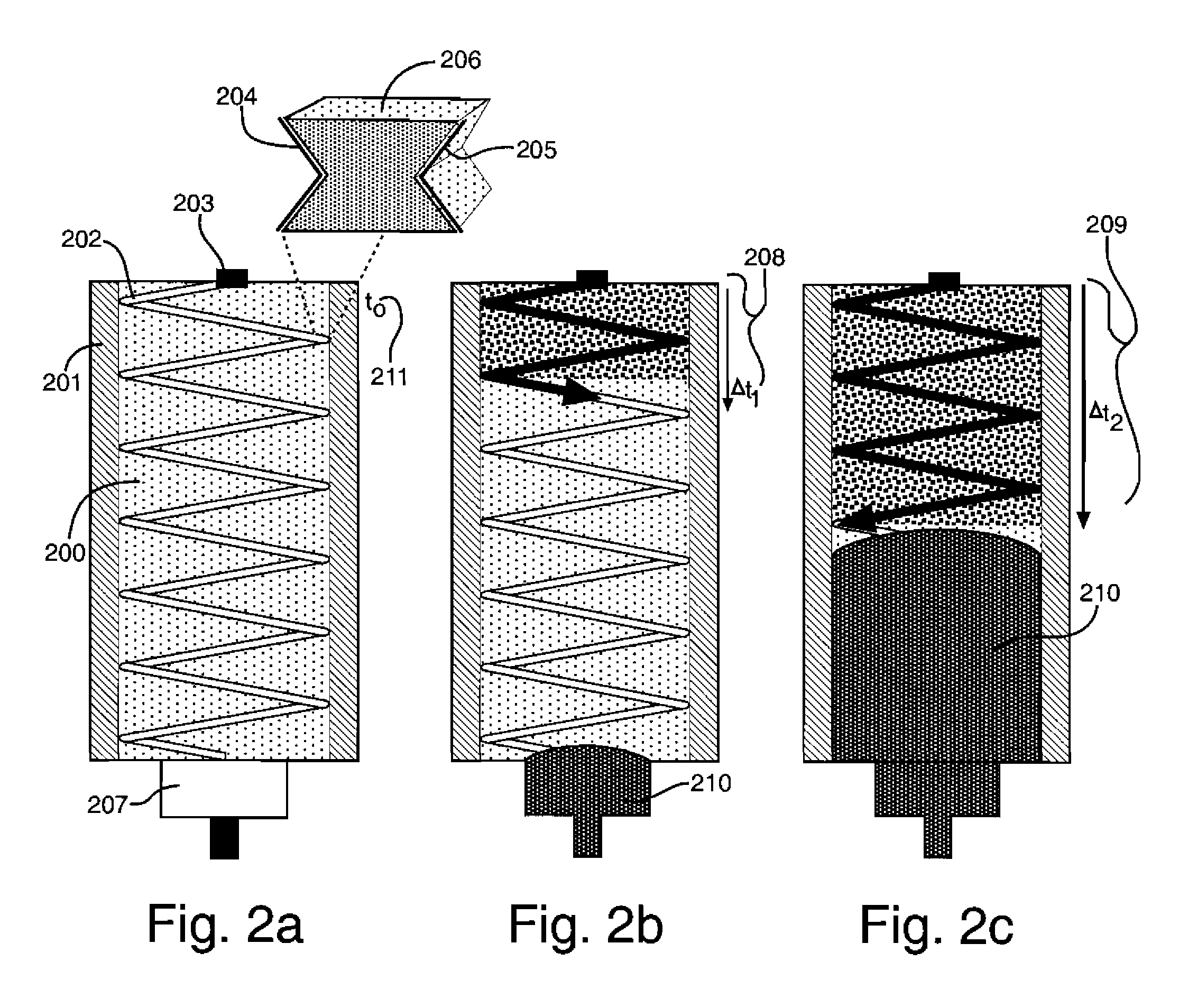
[0006]The invention represents a novel system for controlling the yield of an explosive charge that enables the explosive yield to be selected or decreased from full-yield detonation incrementally down to low-yield detonation using a continuous linear shaped charge jet spiraled around the main charge explosive and deflagrating a selected portion of the main charge explosive.
[0008]It is another object of the invention to provide a system for controlling the yield of an explosive charge that enables the explosive yield to be selected or decreased from full-yield detonation incrementally down to low-yield detonation.
[0009]It is another object of the invention to provide a system for controlling the yield of an explosive charge that enables the explosive yield to be selected or decreased from full-yield detonation incrementally down to low-yield detonation using a continuous linear shaped charge jet spiraled around the main charge explosive and deflagrating a selected portion of the main charge explosive.
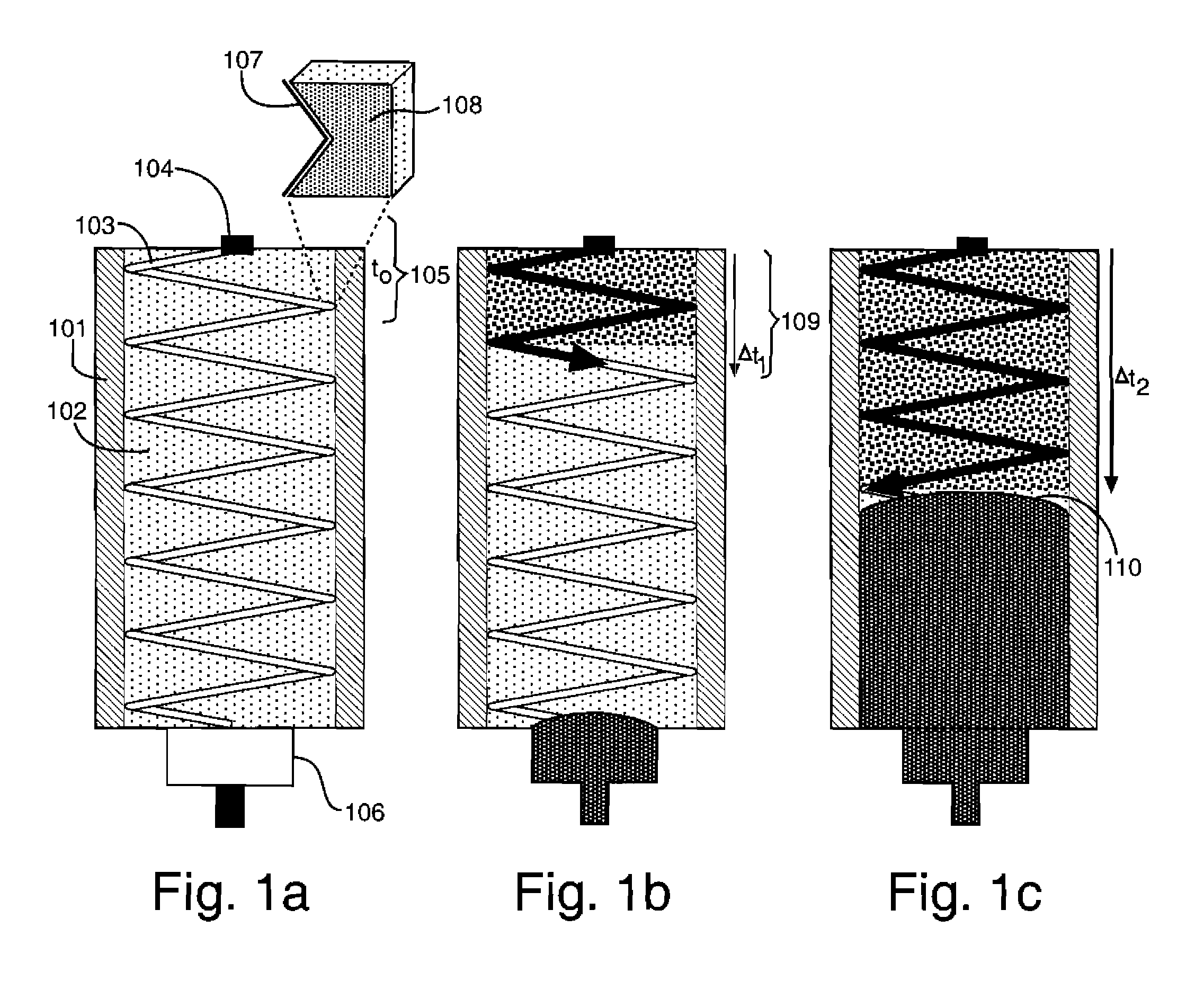
[0016]said spiral linear shaped charge jet initiation system activated and projecting said liner in a radial direction across a diameter of said main charge explosive in a spiral around its axis at a preselected deflagration velocity toward a main-charge detonation shock front reducing said explosive yield by an amount proportional to the volume of explosive deflagrated at a preselected time when the detonated shock front reaches a deflagration interface.

Problems solved by technology

The high pressure, temperature, and friction induced on the main charge from the jet causes the main charge explosive to burn.
In both cases the volume affected by a single shaped charge jet is very limited, and the reaction time is unsuitable for most military applications where a dial-a-yield capability would be useful.

Method used


Image

  • Spiral linear shaped charge jet
  • Spiral linear shaped charge jet
  • Spiral linear shaped charge jet

Examples


Embodiment Construction

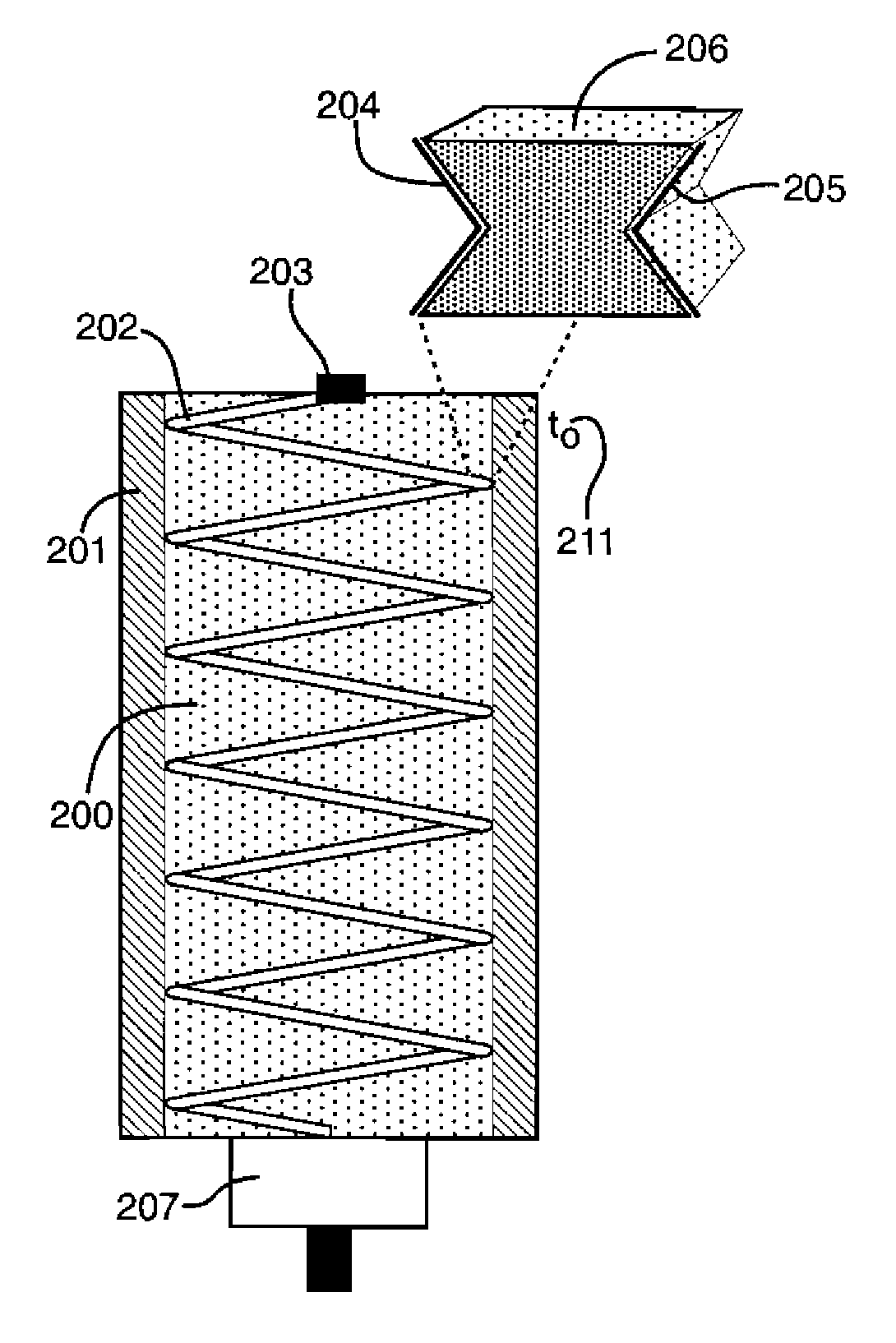
[0029]The system for controlling the yield of an explosive charge described and disclosed herein uses a linear shaped charge jet spiraled around the main-charge of the explosive warhead with liner positioned to shoot across the diameter of the main charge for controlling the yield of an explosive charge. FIGS. 1a-1c shows a drawing of a spiral linear shaped charge jet according to the arrangement of the invention. The main charge case wall is shown at 101 and the main charge within the wall is shown at 102. The spiral linear shaped charge jet is shown at 103 and the spiral linear shaped charge jet initiation system is shown at 104. The main charge detonation system is shown at 106. A magnified view of the spiral linear shaped charge jets' liner interfacing with the explosive is shown at 107 and at 108, respectively.

[0030]The system is initiated at t0, shown at 105, which produces a deflagration reaction along the radial path of the jet through the main-charge 102. FIG. 1b shows the ...


PUM


Abstract

The invention represents a novel system for controlling the yield of an explosive charge that enables the explosive yield to be selected or decreased from full-yield detonation incrementally down to low-yield detonation using a continuous linear shaped charge jet spiraled around the main charge explosive and deflagrating a selected portion of the main charge explosive. The spiral linear shaped charge jet initiation system activates and projects a liner in a radial direction across a diameter of the main charge explosive in a spiral around its axis at a preselected deflagration velocity toward a main-charge detonation shock front reducing the main charge explosive.

Description

RIGHTS OF THE GOVERNMENT[0001]The invention described herein may be manufactured and used by or for the Government of the United States for all governmental purposes without the payment of any royalty.BACKGROUND OF THE INVENTION[0002]The invention relates to selectable-yield munitions and more specifically to spiral linear shaped charge jets.[0003]Explosive ordnance is defined as any component or assembly that contains or is operated by explosive materials. The ability to rapidly release directed energy to perform multiple operations nearly simultaneously is the major attribute of explosive ordnance. To be useful in the aerospace industries and other industries, explosive components' output must be controlled. Selectable-yield munitions have been identified by United States Department of Defense planners as a means to reduce collateral damage while optimizing lethality against a broad target set. Explosively actuated devices are generally lighter and smaller than equivalent mechanic...

Claims


Application Information

Patent Timeline
IPC IPC(8): F42B10/00
CPCF42B1/028
Inventor YELVERTON, JOHN W.
Owner AIR FORCE US SEC THE THE
Learn More