Split heat recovery system

a heat recovery system and split technology, applied in ventilation systems, heating types, lighting and heating apparatuses, etc., to achieve the effects of low manufacturing cost, convenient and efficient manufacturing and marketing, and durable and reliable construction

Active Publication Date: 2011-10-11
TRENT RICHARD W
View PDF14 Cites 14 Cited by
  • Summary
  • Abstract
  • Description
  • Claims
  • Application Information

AI Technical Summary

Benefits of technology

[0021]It is another object of the present invention to provide a new and improved split heat recovery system which may be easily and efficiently manufactured and marketed.
[0022]It is further object of the present invention to provide a new and improved split heat recovery system which is of durable and reliable constructions.
[0023]An even further object of the present invention is to provide a new and improved split heat recovery system which is susceptible of a low cost of manufacture with regard to both materials and labor, and which accordingly is then susceptible of low prices of sale to the consuming public, thereby making such split heat recovery system economically available to the buying public.
[0024]Even still another object of the present invention is to provide a split heat recovery system for transferring heat within heating, ventilating and air conditioning systems without conventionally imposing location restrictions, the transferring being done in a safe, ecological, energy efficient and economical manner.

Problems solved by technology

While these devices fulfill their respective, particular objectives and requirements, the aforementioned patents do not describe a split heat recovery system that allows for transferring heat within heating, ventilating and air conditioning systems without conventionally imposing location restrictions, the transferring being done in a safe, ecological, energy efficient and economical manner.

Method used


Image

  • Split heat recovery system
  • Split heat recovery system
  • Split heat recovery system

Examples


Embodiment Construction

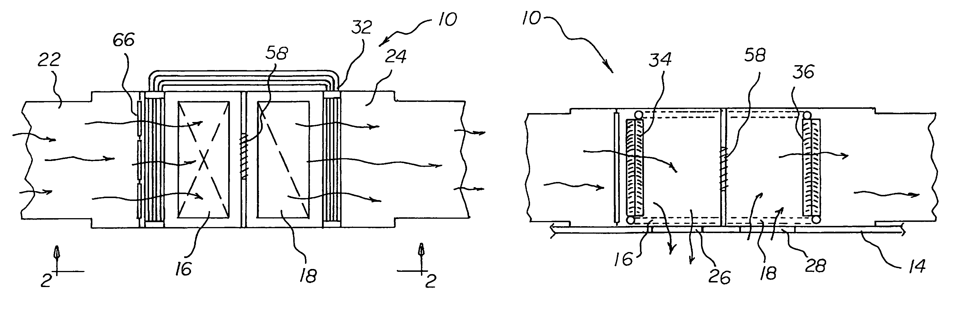
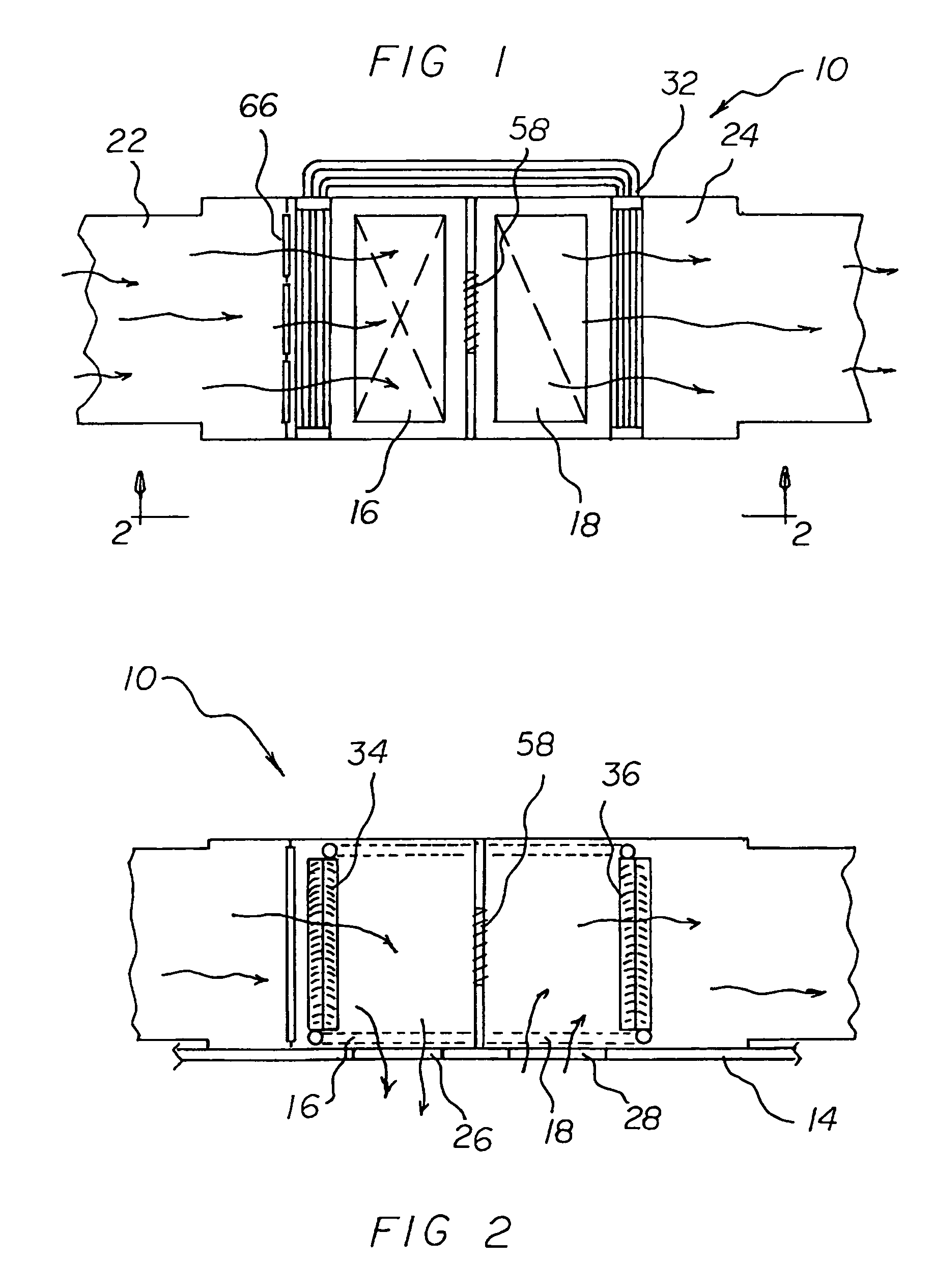
[0037]With reference now to the drawings, and in particular to FIG. 1 thereof, the preferred embodiment of the new and improved split heat recovery system embodying the principles and concepts of the present invention and generally designated by the reference numeral 10 will be described.

[0038]The present invention, the split heat recovery system 10 is comprised of a plurality of components. Such components in their broadest context include a space, a thermosyphon run around heat pipe assembly, a control device and an air filter. Such components are individually configured and correlated with respect to each other so as to attain the desired objective.

[0039]First provided is a room 14. The room has an inlet register 16. In this manner outside air is passed into the room. The room has an outlet register 18. In this manner exhaust air is passed from the room.

[0040]An air duct assembly includes an outside air duct 22. The outside air duct has an open first end. The first end is adapted...


PUM


Abstract

A space has inlet and outlet registers and outside and exhaust air ducts. The outside air duct is located adjacent to the inlet register. The exhaust air duct is located adjacent to the outlet register. The space has an outside air passageway through the outside air duct adjacent to the inlet register. The space has an exhaust air passageway through the exhaust air duct adjacent to the outlet register. A thermosyphon run around heat pipe assembly includes outside air coils and exhaust air coils. Vapor lines and liquid lines couple the coils. The outside air coils are positioned adjacent to the air inlet duct. The exhaust air coils are located adjacent to the air outlet duct. A control device, in the form of a modulating return damper, is located between the air ducts. An air filter is provided upstream of and adjacent to the outside air coils.

Description

BACKGROUND OF THE INVENTION[0001]1. Field of the Invention[0002]The present invention relates to a split heat recovery system and more particularly pertains to transferring heat within heating, ventilating and air conditioning systems without conventionally imposing location restrictions, the transferring being done in a safe, ecological, energy efficient and economical manner.[0003]2. Description of the Prior Art[0004]The use of heat transferring systems of known designs and configurations is known in the prior art. More specifically, heat transferring systems of known designs and configurations previously devised and utilized for the purpose of transferring heat through known methods and apparatuses are known to consist basically of familiar, expected, and obvious structural configurations, notwithstanding the myriad of designs encompassed by the crowded prior art which has been developed for the fulfillment of countless objectives and requirements.[0005]By way of example, U.S. Pa...

Claims


Application Information

Patent Timeline
Patent Type & Authority Patents(United States)
IPC IPC(8): F24F7/007
CPCF24F12/002Y10S165/909Y02B30/563F24F2012/007Y02B30/56
Inventor TRENT, RICHARD W.
Owner TRENT RICHARD W
Why Eureka
Try Eureka