Custom impression coping and methods of manufacture and use thereof

a technology of impressions and copings, applied in the field of custom impressions, can solve the problems of inaccurate impressions, more difficult parts of teeth or tooth abutments to accurately take, and interfere with the taking of impressions, etc., and achieve the effect of accurate impressions

Inactive Publication Date: 2011-10-11
COOPERSMITH ALLAN
View PDF3 Cites 2 Cited by
  • Summary
  • Abstract
  • Description
  • Claims
  • Application Information

AI Technical Summary

Benefits of technology

[0013]It is therefore an object of the present invention to provide an improved method of creating a tooth impression.

Problems solved by technology

One of the more difficult parts of the tooth or tooth abutment to accurately capture in the area around the base of tooth, and particularly in the area at the base of the tooth next to another tooth.
This groove interferes with the taking of an impression.
(Although some dentists claim that they can take impressions without the step of retraction, those impressions are often inaccurate and faulty, and depend on what is known in the art as a “total wash technique”, using a low durometer material placed into a pre-set high durometer material, that creates a casting which is too tight and has an inaccurate fit.)
Unfortunately, all current retraction systems and techniques have drawbacks.
For example, most cord-type retraction systems are tedious, ineffective and traumatic to tissues.
The cartridges and the gun are expensive, and often break.
The Kaolin is difficult to insert into the sulcus and requires rinsing and drying which often creates additional unwanted bleeding.
This process is, however, time consuming and expensive and compresses the gingival in an inaccurate, ineffective and unpredictable manner.
This causes the sulcus to partially collapse and renders a less accurate impression.
Additionally, the same pressure is exerted on the abutments as is placed on the adjacent teeth which leads to inaccuracies and loss of operator control.
Most two step impression techniques are inaccurate in that the primary or preliminary impression is allowed to set over the teeth or gingiva to be restored, and then said impression is filled with a wash or impression material of a lesser durometer and reseated.
Undercuts in the teeth and surrounding structures prevent the re-seating of the secondary impression leading to distortion and inaccuracies.
Both of these inventions, however, require additional steps, are expensive, non-precise, inaccurate, and do not provide for simultaneous retraction as well as impression of the teeth and supporting structures.
The result is frequent entrapment of bubbles and defective margins.
When no spacer is utilized, two step impression techniques create inaccuracies and excessively tight fitting castings in that the softer or lower durometer wash impression material is overly compressed.
The difficulty with retraction caps is that the shape of the cap is even and constant while that of the sulcus (both depth and width) is not.
Therefore this method is imprecise and does not ensure accurate nor sufficient retraction.
These procedures, however, are not without their drawbacks as well.
Electric bistoury and laser generally mutilate the gingival tissue and are therefore quite painful and require local anaesthesia.
Similarly diamond curettage is also quite painful and causes prolific bleeding.
Each of these procedures is traumatic and creates gingival shrinkage and recessions leading to undesirable unprotected root coverage.
It did leave one drawback, namely that it was still an extra step in the process of creating an impression.

Method used


Image

  • Custom impression coping and methods of manufacture and use thereof
  • Custom impression coping and methods of manufacture and use thereof
  • Custom impression coping and methods of manufacture and use thereof

Examples


Embodiment Construction

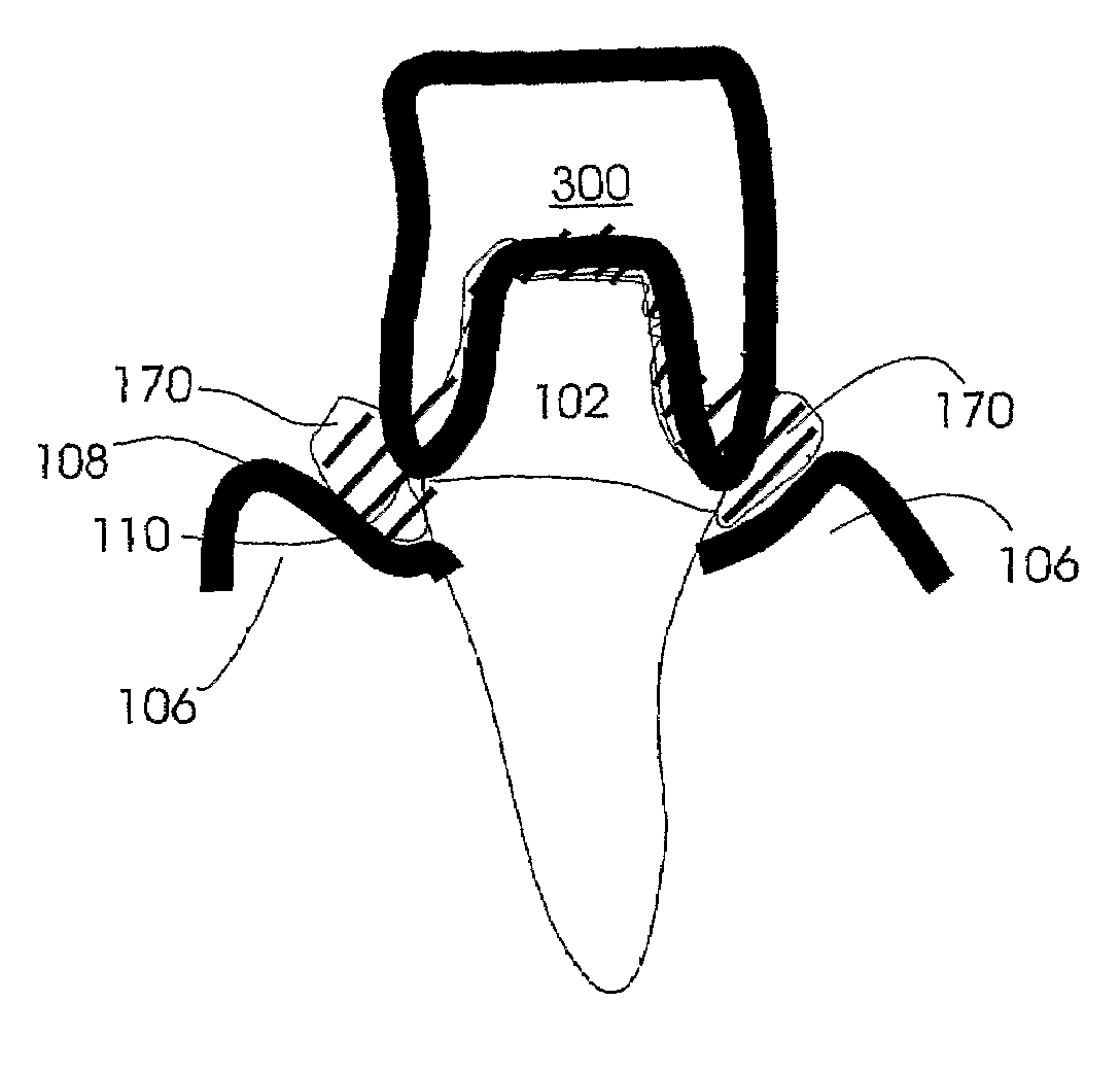
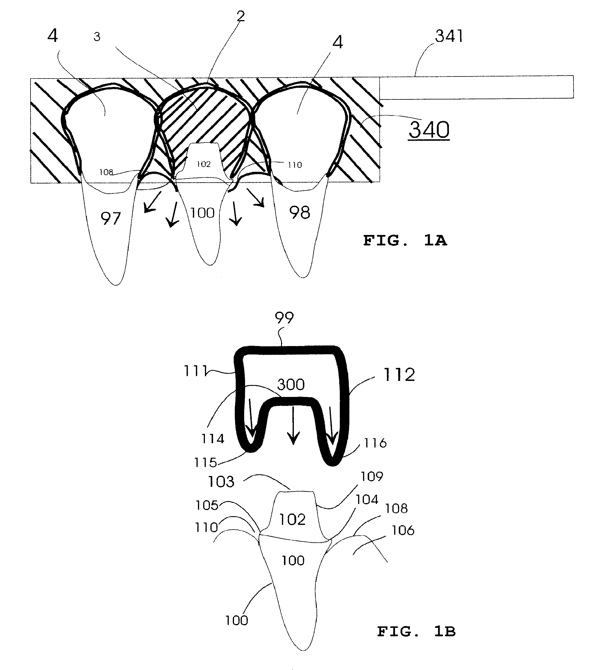
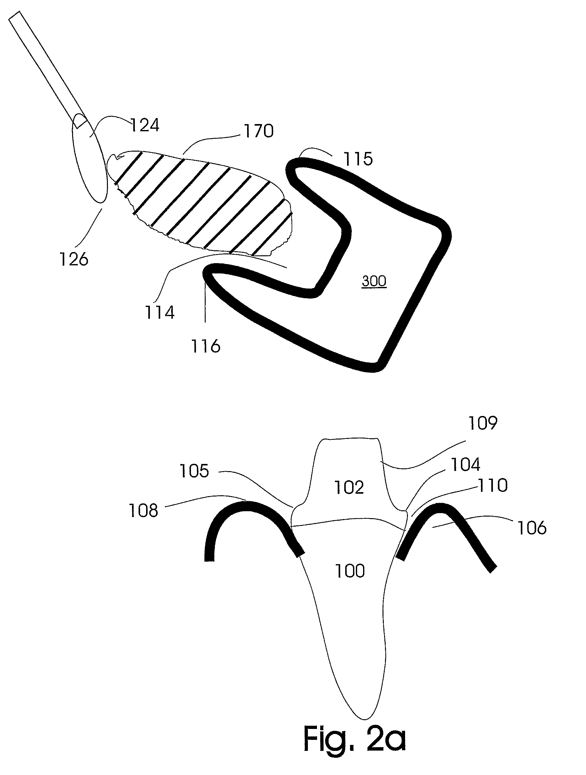
[0114]FIG. 1a illustrates the fabrication of a custom impression coping 2 which has been fabricated by placing an unset retraction / impression material 3 into a set or hardened preliminary impression 340, which has been fabricated by taking an impression of the tooth to be prepared 100 including the adjacent teeth 97 and 98, using an impression material contained in an impression tray 341. The unset retraction-impression material 3 has been placed into the cavity 2 corresponding to the prepared tooth abutment 102 of the preliminary impression 340 and then the impression tray 341 is replaced back over the teeth compressing the unset retraction / impression material 3 over the prepared tooth abutment 102 and into the sulcus 110, thereby capturing the form of the abutment 102, the abutment margins 104 and 105. The retraction / impression material 3 is placed only in the cavity corresponding to the prepared tooth abutment 102. The cavity 4 of the adjacent teeth is not filled with the retract...


PUM


Abstract

A device for retracting gingival tissue away from a tooth or plurality of teeth prepared to receive a dental prosthesis comprising a retraction / impression material associated with a custom impression coping to be packed into a sulcus associated with the prepared tooth, and coincidentally obtaining an impression of said tooth or teeth. The device is preferably compressible, deformably rigid, extensile and non-elastic and will not stick to the gingiva or tooth structure thereby allowing for atraumatic removal. A method of use is also disclosed.

Description

CROSS-REFERENCE TO RELATED APPLICATIONS[0001]The present application is a 371 national stage of International Application No. PCT / CA06 / 001821, filed Oct. 30, 2006, which claims the benefit of priority to U.S. Provisional Patent Application No. 60 / 730,883, filed Oct. 28, 2005. It is related to, but does not claim the benefit of priority to, the following applications: Unites States Patent Application Publication No. 2005-0118552-A1, entitled “Gingival Retraction Device and Method”, published Jun. 2, 2005; U.S. Pat. No. 7,033,173, entitled “Gingival Retraction Device and Method”, published Apr. 25, 2006; and International Patent Application Publication No. WO / 2002 / 102269, entitled “Gingival Retraction Device and Method”, published Dec. 27, 2002. The contents of all of the aforementioned patents and patent applications are incorporated herein by reference.FIELD OF THE INVENTION[0002]The present invention relates to devices and methods employed by dental practitioners during dental proc...

Claims


Application Information

Patent Timeline
Patent Type & Authority Patents(United States)
IPC IPC(8): A61C9/00
CPCA61C8/0001A61C9/0033A61C9/00
Inventor COOPERSMITH, ALLAN
Owner COOPERSMITH ALLAN
Why Eureka
Try Eureka