Method and device for measuring internal impedance of stationary battery

a technology of internal impedance and measuring device, which is applied in the direction of measurement device, scientific instruments, instruments, etc., can solve the problems of difficult to increase the accuracy of the measured value in comparison to the ac current injection method, take a long time for measuring and calculating, etc., and achieve the effect of easy installation and minimizing the effect of measuring error due to the change of surrounding temperatur

Inactive Publication Date: 2011-10-11
INCELLS
View PDF13 Cites 19 Cited by
  • Summary
  • Abstract
  • Description
  • Claims
  • Application Information

AI Technical Summary

Benefits of technology

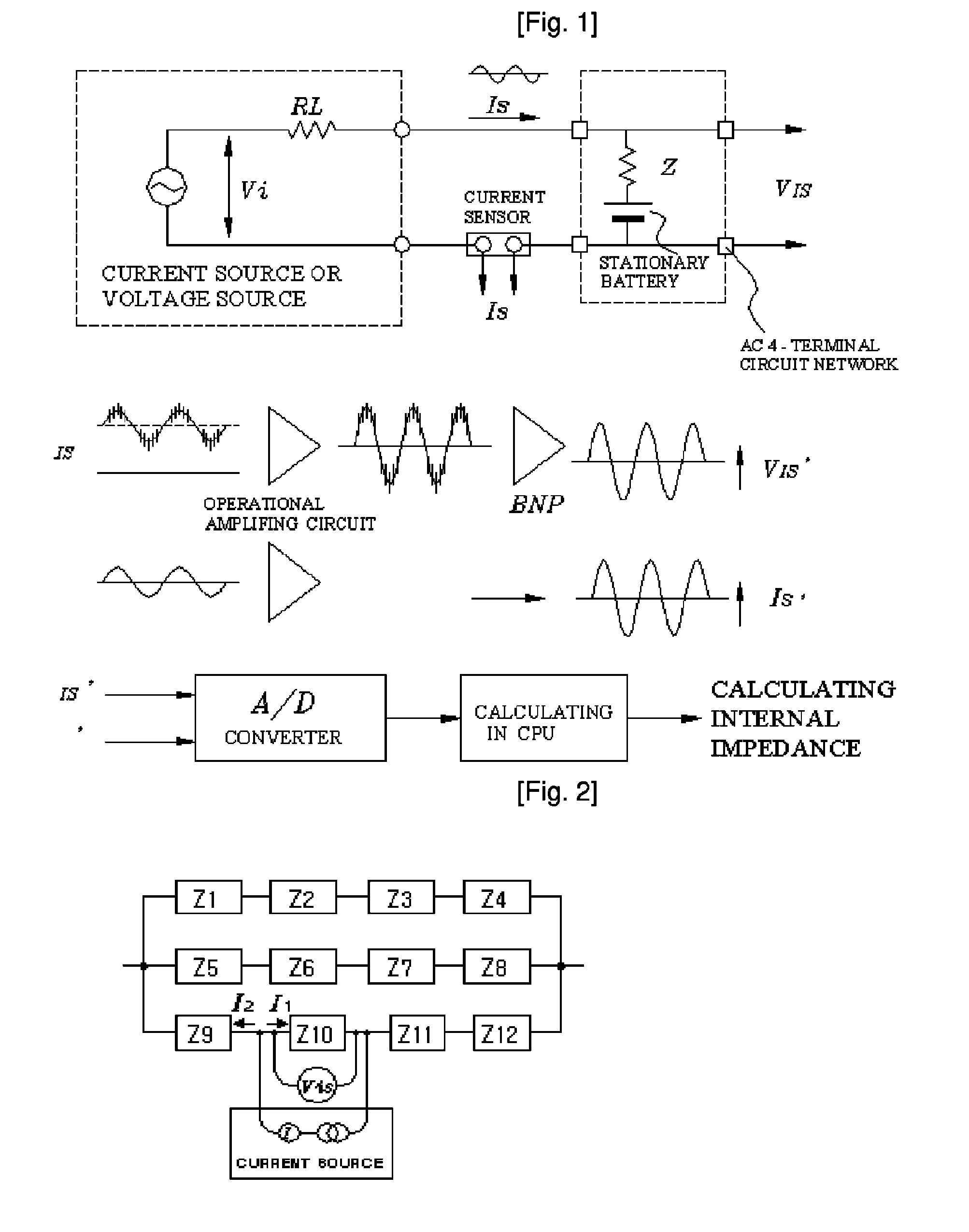
[0027]As described above, according to the present invention, when a large number of stationary battery cells is measured on-line, by using a measuring circuit, a direct current (DC) current waveform contains a charging ripple current generated from a string of stationary batteries during the charging is detected by a current sensing means such as a shunt or a DC converter (DC.CT), a measuring signal corresponding to the sine wave AC current (IS) and the measuring frequency component, required to measure the impedance voltage (VIS) generated by the sine wave AC current (IS), can be obtained, and the internal impedance or effective value (resistance component) thereof can be precisely calculated through the calculating algorithm.
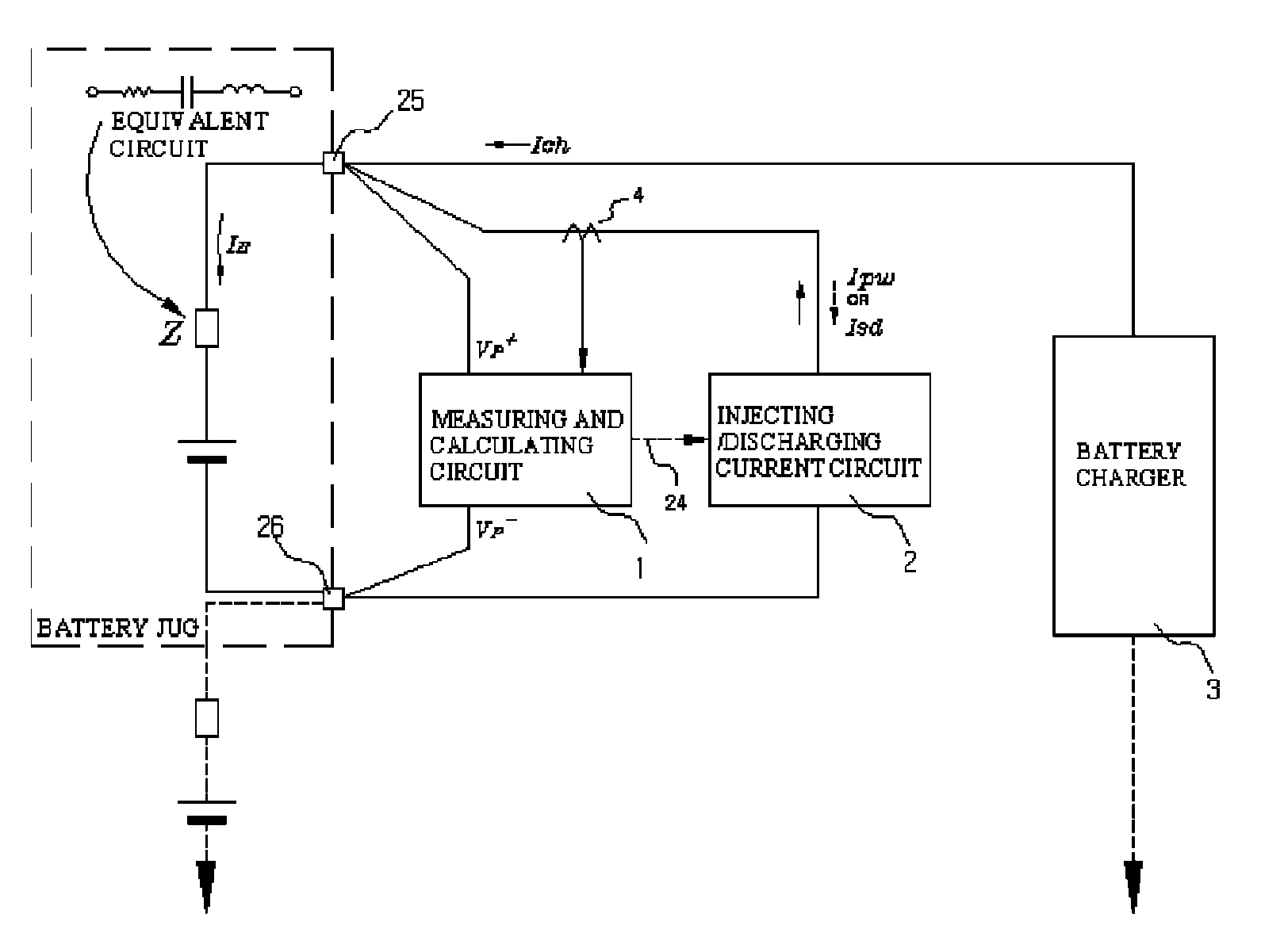
[0028]Moreover, according to the present invention, the current sensing means is installed to an output terminal of the current injection / discharge circuit 2 and a pulse width modulation (PWM) measuring signal having an optimally designed frequency is injected or discharged through the 4-terminal circuit network to become the PWM current so that the internal impedance on a corresponding measuring frequency can be measured without a hardware circuit device to generate the sine wave AC current Is.
[0029]Further, the fundamental frequency of the square wave current that is injected to or discharged from the stationary battery cell to be measured and the square wave PWM pulse width control frequency is designed optimally to use a common band pass filter circuit. Therefore, since the measuring error due to change of surrounding temperature can be minimized, it is advantageous in economical view.
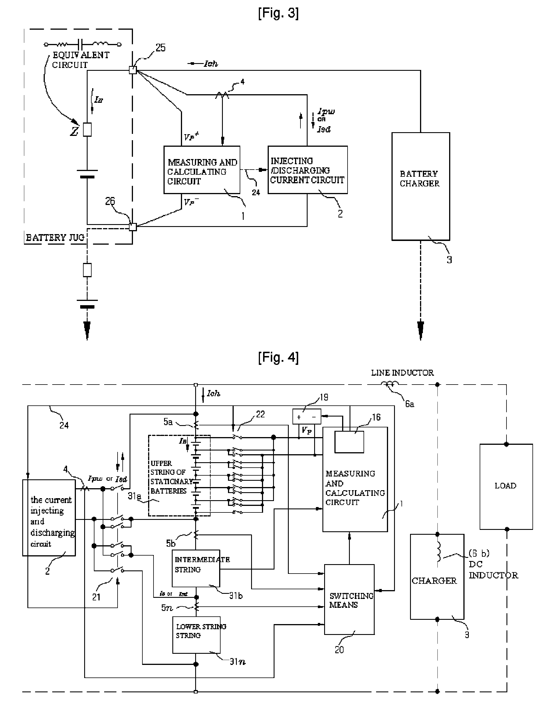
[0030]Moreover, since the current sensing circuit is installed to an adjacent point of a positive bus or a negative bus of the stationary batteries or the string of stationary batteries or an intermediate point of the string of stationary batteries, a measuring signal cabling through the 4-terminal circuit network can be remarkably reduced and their installation is very easy. A circuit is formed to detect the output current of the current injecting and discharging circuit 2 and a charging ripple current IRP simultaneously, so that the impedance voltage VIS component generated by the charging ripple current IRP helps to measure and calculate the internal impedance value. Therefore, the influence from the harmonics ripple voltage VRP can be excluded on the way of calculation.
[0031]Moreover, in the case where a large number of battery cells is connected to each other in series or in parallel like a stationary battery system in which a large number of strings to be measured, which are connected to each other in series, is connected to each other in parallel, since the large number of stationary battery cells is precisely measured by the current sensing means connected to the strings that are connected to each other in series by blocks without the measuring signal I distributed to another battery string or another power source side, there is no need to perform the correction factor of the value calculated by experience like the conventional method and the measured value is reliable.
[0032]Further, according to the present invention, the current injecting and discharging circuit is designed to generate the square wave injection current or the discharge current having a small section in the circuits so that the size of the devices for measuring and calculating the internal impedance of the stationary battery can be reduced.

Problems solved by technology

However, since the voltage on the terminals of the stationary battery jug is changed in accordance with a charging status and the discharge status when the floating charge is performed, it is difficult to increase the precision of the measured value in comparison to the AC current injection method, and it takes a long time for measuring and calculating.

Method used


Image

  • Method and device for measuring internal impedance of stationary battery
  • Method and device for measuring internal impedance of stationary battery
  • Method and device for measuring internal impedance of stationary battery

Examples


Embodiment Construction

ed by a pulse width modulation chopping for a 120 degrees conduction period;

[0041]FIG. 9 is a graph illustrating variations of magnitudes of a harmonics at respective frequencies in accordance with On-duty variations of a pulse width modulation in FIG. 8;

[0042]FIG. 10 is a view illustrating spectra of the harmonics as to respective frequencies in accordance with waveform distortion of a square wave current chopped by the pulse width modulation in FIG. 8;

[0043]FIG. 11 is a view illustrating spectra of respective harmonics as to a current waveform chopped by the pulse width modulation for a 180-degrees period and off-pulsed for 180-degrees half-period thereafter;

[0044]FIG. 12 is a graph illustrating magnitude variations of the harmonics at respective frequencies in accordance with the variations of the pulse width modulation On-duty in FIG. 11; and

[0045]FIG. 13 is a flowchart schematically illustrating a measuring and calculating method according to the present invention.

BEST MODE FOR...


PUM


Abstract

Battery system is widely used in emergent power plant or communication network power plant and its effective management is important. When any one of batteries connected to each other in series is failed during operation of the battery system, since reliability of the system cannot be secured, a problem is arisen to stable operation of the communication network. In a method of separating inferior battery, the battery is operated in floating charge state without separation to generate square current containing charge current and easily generated to flow through the battery cell, voltage signal generated from terminal voltage of the battery by the measuring signal is processed such that only internal impedance voltage signal is separated from harmonics ripple voltage and noise voltage by a synchronized detection calculating algorithm to calculate the internal impedance or effective value thereof (resistance component). When the algorithm is applied after filtering only fundamental frequency and similar component by general filter, measuring precision can be improved and measuring time can be reduced.

Description

TECHNICAL FIELD[0001]The present invention relates to an apparatus for measuring an effective component of internal impedance of a stationary battery and a method thereof and, more particularly, to an apparatus for measuring an effective component of the internal impedance of a stationary battery, which is capable of generating an injection current and a discharge current of a square wave to calculate the internal impedance or the effective value of the internal impedance of a stationary battery or a string of stationary batteries and a method thereof.BACKGROUND ART[0002]In general, in order to determine the status of deterioration of respective cells that constitute an industrial stationary battery system, the value of internal impedance or conductance is measured. An alternating current (AC) current injection method and a momentary load test; direct current (DC) current measurement are mainly used for measuring the values of the internal impedance and the conductance.[0003]At this...

Claims


Application Information

Patent Timeline
Patent Type & Authority Patents(United States)
IPC IPC(8): G01N27/416
CPCG01R31/3627G01R31/3662G01R31/3679G01R31/3658G01R31/385G01R31/392G01R31/396G01R31/389G01R31/36
Inventor KIM, DEUK SOO
Owner INCELLS
Why Eureka
Try Eureka