Printed circuit board for optical waveguides and method of manufacturing the same
a printed circuit board and waveguide technology, applied in the field of printed circuit boards for optical waveguides, can solve the problems of low bending reliability of printed circuit boards including existing optical waveguides, and achieve the effects of preventing circuit patterns from being broken, improving bending reliability of printed circuit boards, and reducing the effect of stress on circuit patterns
- Summary
- Abstract
- Description
- Claims
- Application Information
AI Technical Summary
Benefits of technology
Problems solved by technology
Method used
Image
Examples
first embodiment
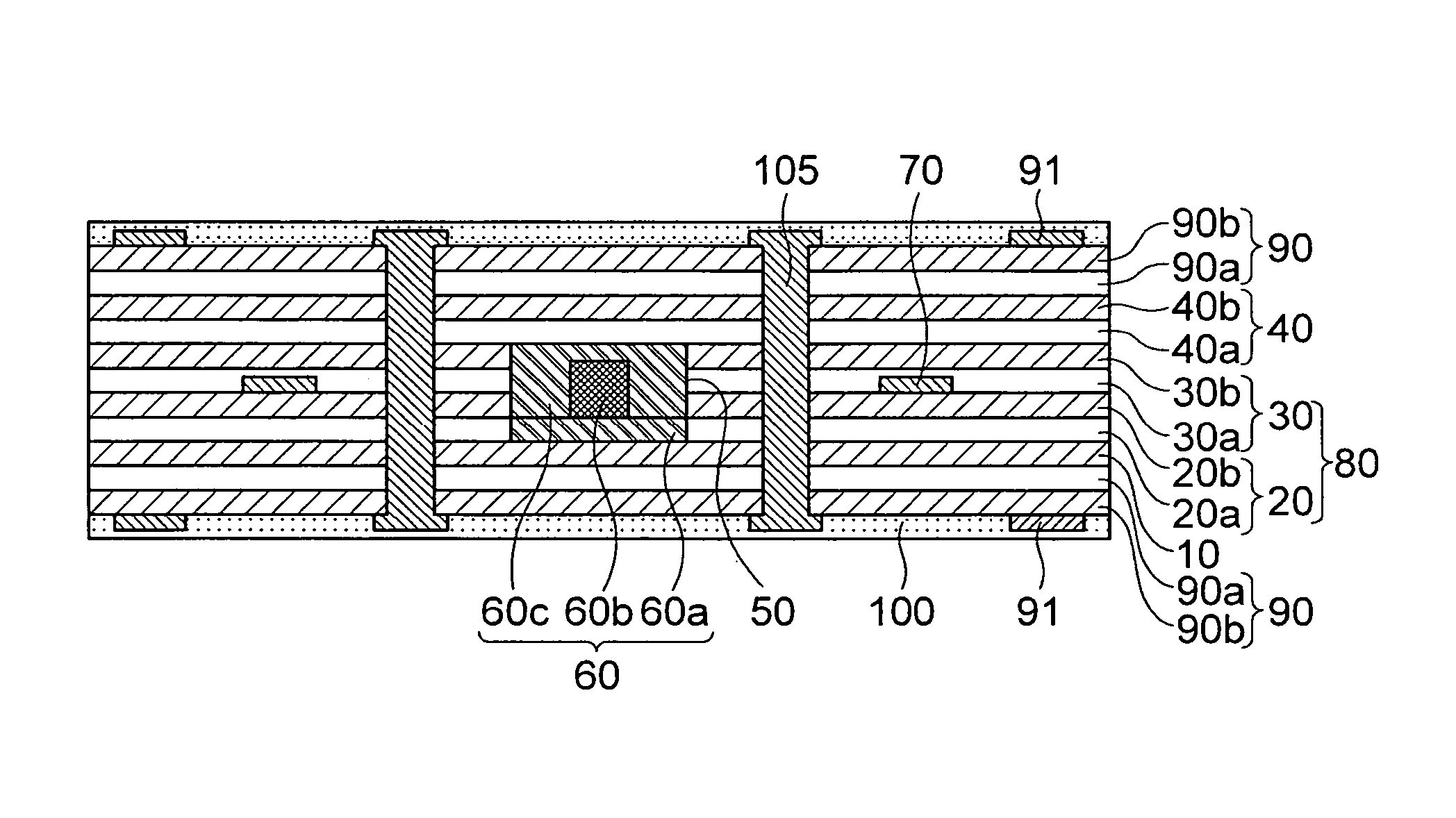
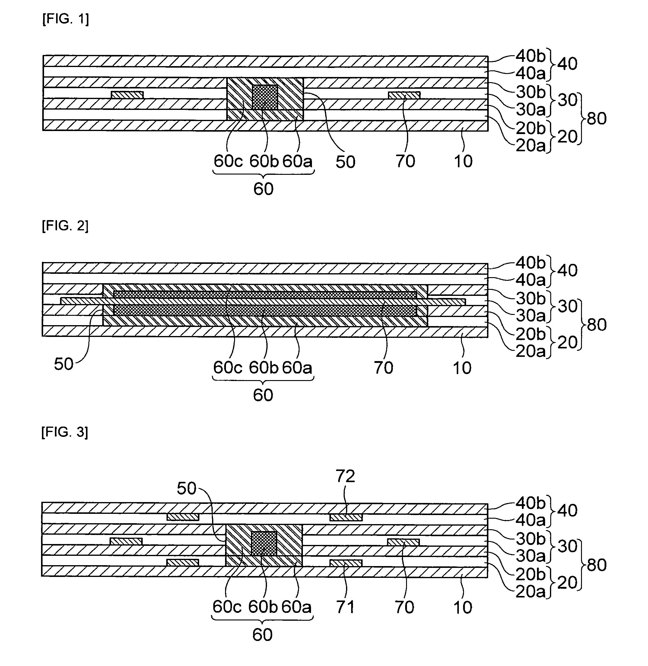
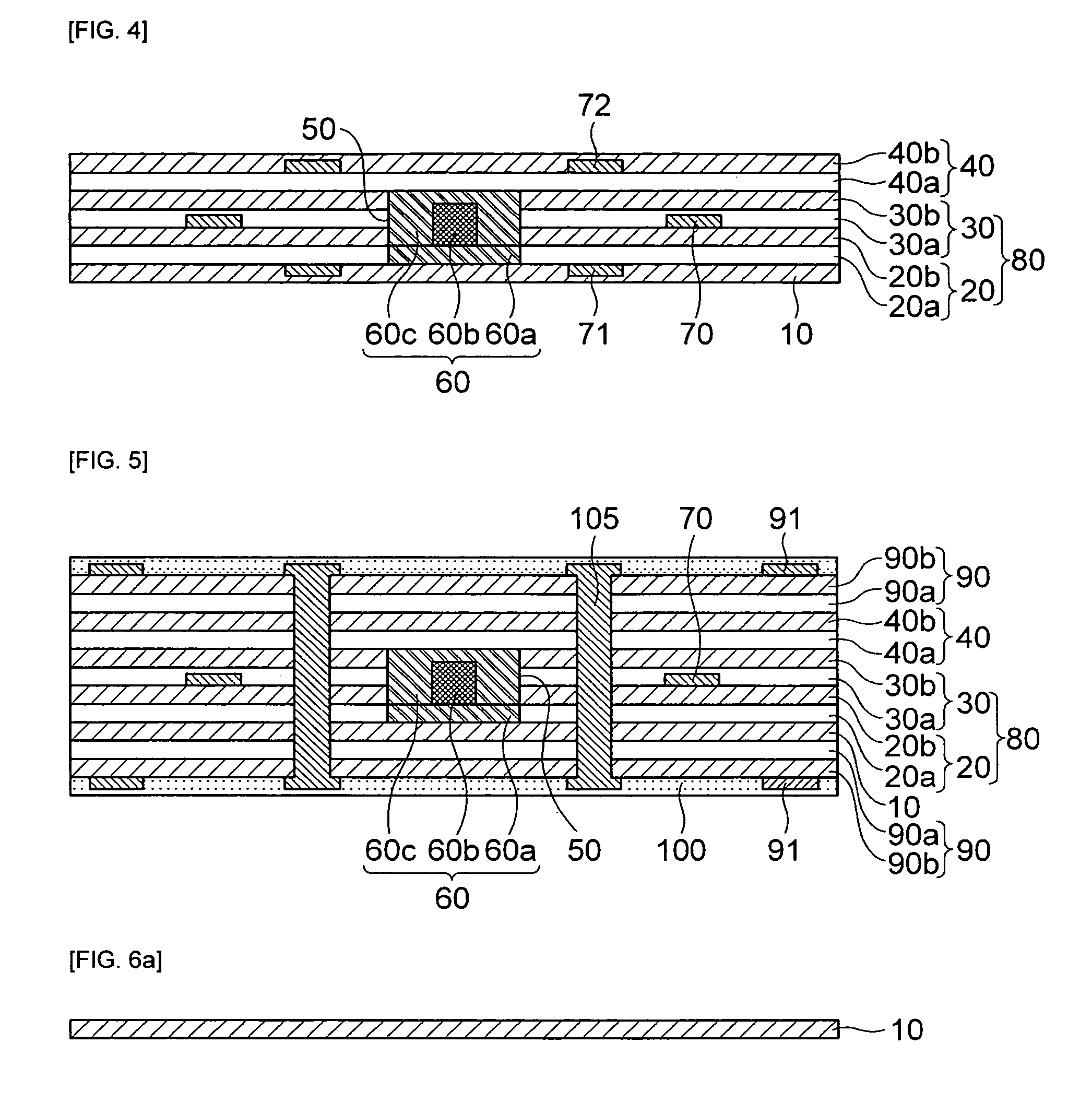
[0059]First, the printed circuit board for optical waveguides according to the present invention includes a base substrate 10, an optical waveguide 60 that is formed on an upper middle of the base substrate 10, and a side substrate 80 that is formed on the base substrate 10, has a through hole 50, through which the optical waveguide 60 penetrates, at a middle thereof, and has a first circuit pattern 70 formed inside the side substrate 80, as shown in FIGS. 1 and 2.
[0060]An upper substrate 40 is formed on the side substrate 80 including the optical waveguide 60. Herein, the upper substrate 40 may not be formed.
[0061]The base substrate 10 may be made of an insulating layer such as polyimide, etc. In addition, the base substrate 10 may be made of a metal foil, such as a copper foil (Cu foil), etc., instead of the insulation layer or may be made of a laminate material of the insulating layer and the metal foil, etc.
[0062]The optical waveguide 60 formed on the base substrate 10 includes ...
second embodiment
[0080]Next, a printed circuit board for optical waveguides according to the present invention will be described in detail with reference to FIG. 3.
[0081]As shown in FIG. 3, a configuration of the printed circuit board for optical waveguide according to the second embodiment of the present invention is approximately similar to the configuration of the printed circuit board of optical waveguides according to the first embodiment of the present invention. However, the second embodiment is different from the first embodiment only in that it further includes a second circuit pattern 71 formed inside the side substrate 80 and having a lower surface contacting the upper surface of the base substrate 10.
[0082]Herein, the second circuit pattern 71 may be formed inside the first adhesive layer 20a configuring the side substrate 80.
[0083]Further, the printed circuit board for optical waveguides according to the second embodiment of the present invention may further include a third circuit patt...
third embodiment
[0085]Next, the printed circuit board for optical waveguides according to the present invention will be described in detail with reference to FIG. 4.
[0086]As shown in FIG. 4, a configuration of the printed circuit board for optical waveguide according to the third embodiment of the present invention is approximately similar to the configuration of the printed circuit board of optical waveguides according to the second embodiment of the present invention. However, the fourth embodiment is different from the first embodiment only in that the second circuit pattern 71 is formed inside the base substrate 10, instead of being formed inside the side substrate.
[0087]In other words, according to the third embodiment of the present invention, the second circuit pattern 71 may be formed inside the base substrate 10 and the upper surface of the second circuit pattern 71 may contact the lower surface of the side substrate 80.
[0088]Further, the printed circuit board for optical waveguides accord...
PUM
| Property | Measurement | Unit |
|---|---|---|
| thickness | aaaaa | aaaaa |
| adhesive | aaaaa | aaaaa |
| insulating | aaaaa | aaaaa |
Abstract
Description
Claims
Application Information
 - R&D
- Intellectual Property
- Life Sciences
- Materials
- Tech Scout
- Unparalleled Data Quality
- Higher Quality Content
- 60% Fewer Hallucinations
Browse by: Latest US Patents, China's latest patents, Technical Efficacy Thesaurus, Application Domain, Technology Topic, Popular Technical Reports.
© 2025 PatSnap. All rights reserved.Legal|Privacy policy|Modern Slavery Act Transparency Statement|Sitemap|About US| Contact US: help@patsnap.com


