Adjustable air conditioning control system for a universal airplane ground support equipment cart

a control system and airplane technology, applied in the direction of ducting arrangement, domestic cooling equipment, lighting and heating equipment, etc., can solve the problems of not being able to provide liquid coolant for critical electronic components, unable to meet and the cart designed to support the specific requirements and needs of the first type or class of airplane cannot be used to support the differing specific requirements and needs of the other types or classes of airplanes

Inactive Publication Date: 2011-10-18
ILLINOIS TOOL WORKS INC
View PDF31 Cites 6 Cited by
  • Summary
  • Abstract
  • Description
  • Claims
  • Application Information

AI Technical Summary

Problems solved by technology

When an airplane is on the ground with its engines shut down, the airplane is typically unable to provide power for its electrical systems and chilled air for its air conditioning systems; and some airplanes are also unable to provide liquid coolant for some critical electronic (or “avionic”) components.
Hence, a cart designed to support the specific requirements and needs of a first type or class of airplane cannot be used to support the differing specific requirements and needs of other types or classes of airplanes.
Problems arise when more airplanes of a particular type arrive at a specific location than there are ground support equipment carts suitably designed to service the needs of that particular type or class of airplane.
Since the temperature and pressure and fluid flow volume requirements for PAO cooling may vary from one type or class of airplane to the next, a PAO cooling system designed to meet the specialized PAO cooling needs of one airplane will not necessarily meet the somewhat different needs of another type or class of airplane.
This intermixing of non-air-conditioning components with the air-conditioning components greatly complicates servicing of all the components, since they are all crowded into the same cramped space.
If such a system has its cool air ducted into some other type or class of airplane, too much or too little air will flow from the air conditioner system, and this will throw off the balance of the air conditioning system, causing the air to be cooled too little or too much and possibly causing icing of the internal evaporators or damage to the airplane.
And the temperature and pressure provided may not be proper for some other type or class of airplane.
Likewise, the electrical systems may not be able to supply the needs of differing types or classes of airplanes, and the PAO liquid cooling system may not be properly balanced when used to cool the avionics of differing types or classes of airplanes.

Method used


Image

  • Adjustable air conditioning control system for a universal airplane ground support equipment cart
  • Adjustable air conditioning control system for a universal airplane ground support equipment cart
  • Adjustable air conditioning control system for a universal airplane ground support equipment cart

Examples


Embodiment Construction

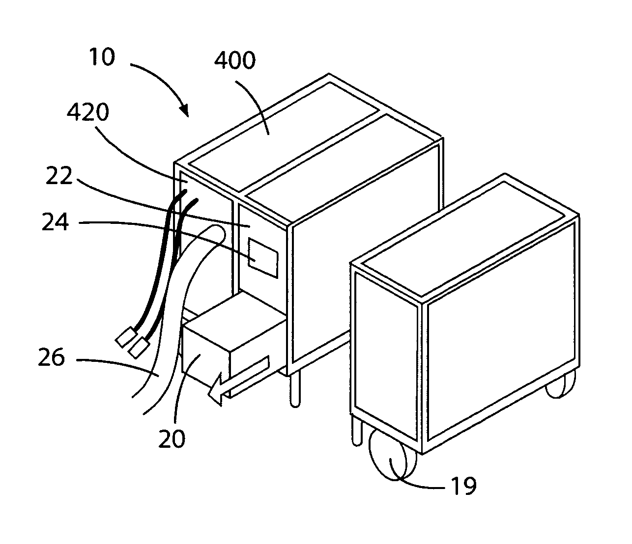
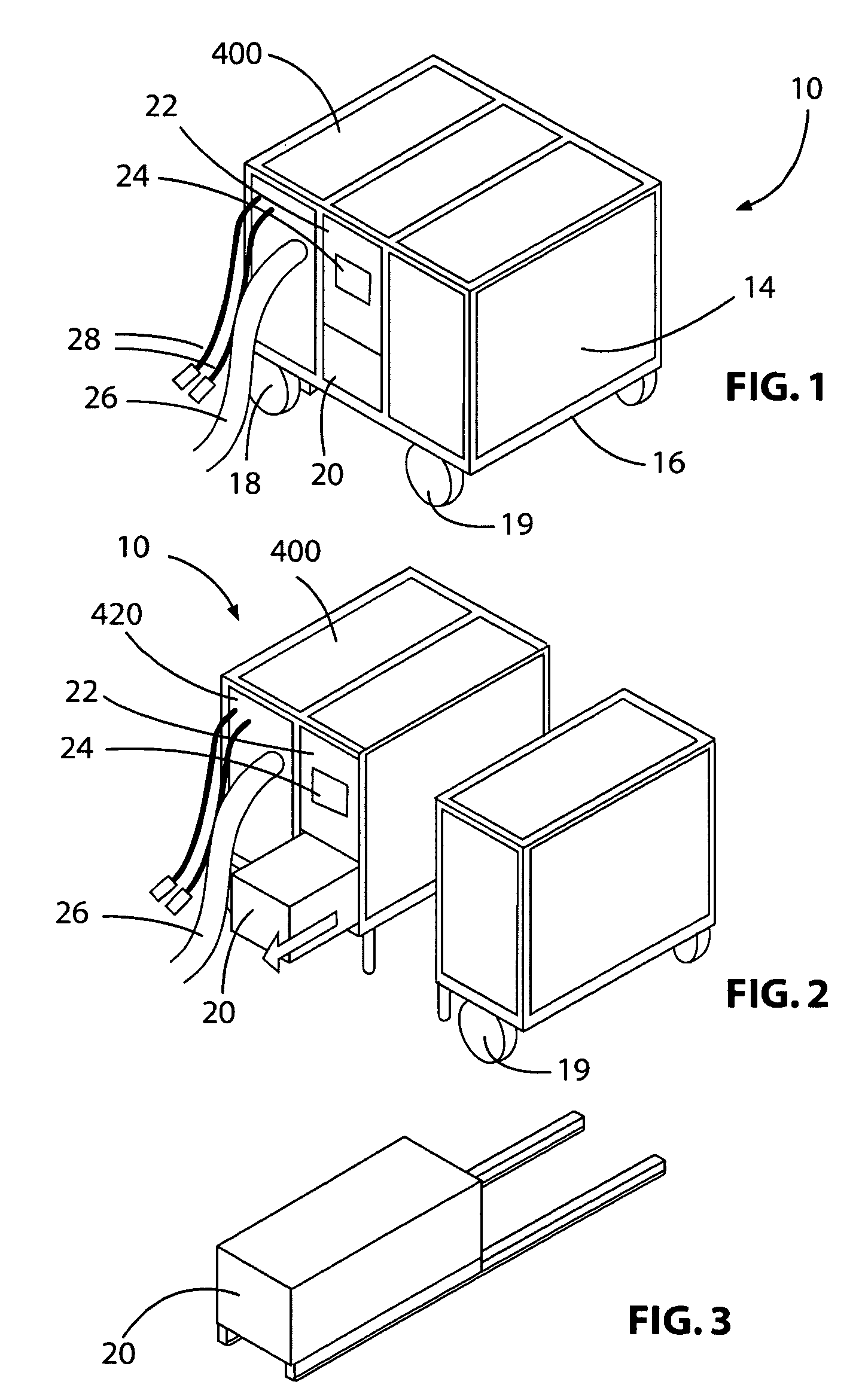
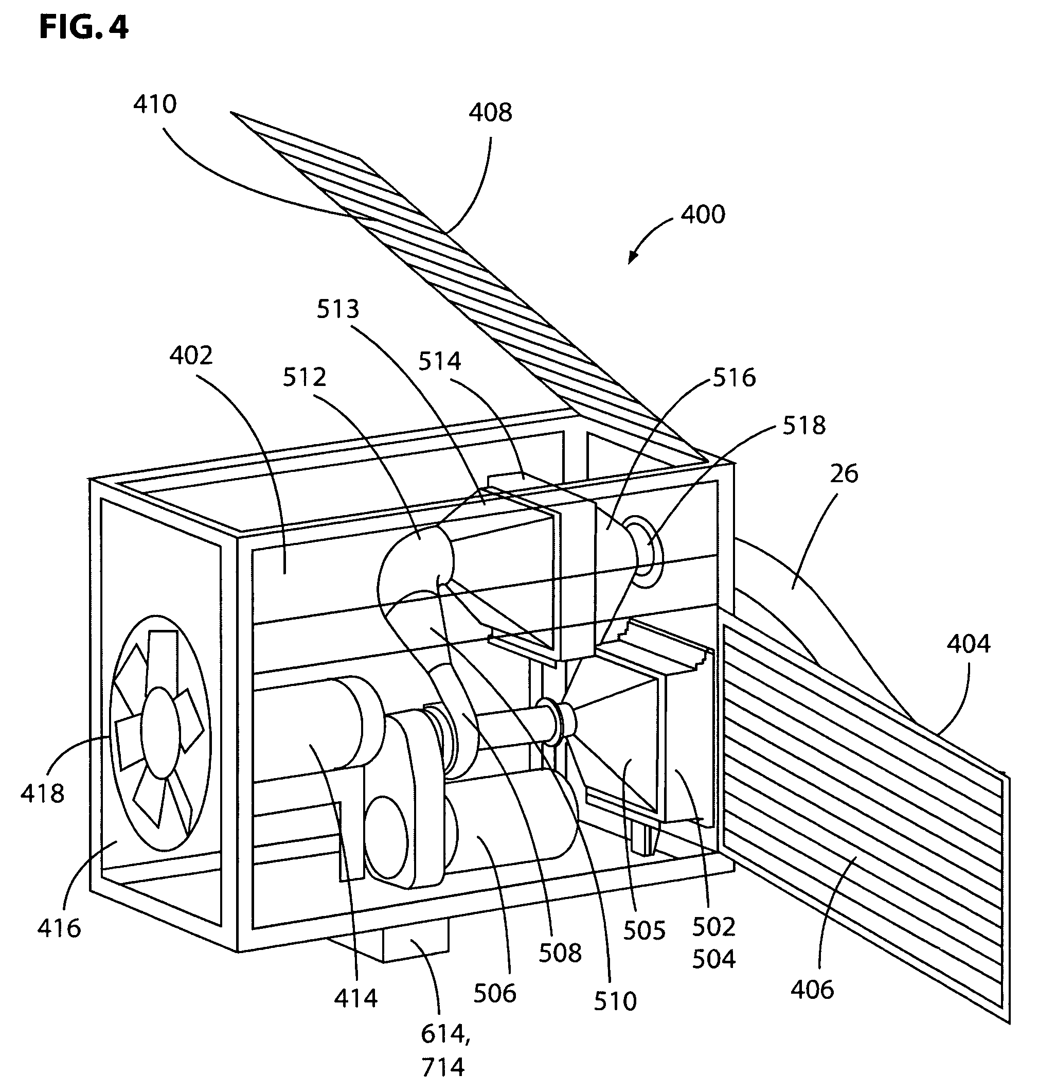
[0045]The detailed description which follows is broken into two sections. Section A presents an introduction to the environment of the present invention, which relates to the design of an adjustable air conditioning control system for a modularized universal airplane ground support equipment cart (FIGS. 1-3). Section B presents a detailed description of the air conditioning control system in the context of the complete ground support air conditioning system, including that system's internal mechanical details (FIGS. 1-4, 9-12, and 29), air flow details (FIG. 5), refrigerant and PAO coolant flow path details (FIGS. 6-8), electronic control system details (FIGS. 13-19), and display system and human interaction details (FIGS. 20-28). The focus of the present invention is the air conditioner control system (disclosed in a somewhat simplified form in FIG. 15, with various details disclosed in many of the other figures).

A. Modular and Universal Airplane Ground Support Equipment Cart

[0046]...


PUM


Abstract

A ground support equipment air conditioning system detachably connects to a port on an airplane. An air conduit connects an air intake and filter to a coupling that is adapted to be connected to one end of an air duct or hose the other end of which is adapted to be connected to an airplane's port. A variable speed blower in the air conduit has its speed varied by a controller to regulate the pressure supplied to an airplane. This controller receives as inputs the pressure sensed by a pressure sensor connected to the air conduit adjacent the coupling to sense the pressure of air passing into the airplane and also a setpoint pressure which can be varied to match the requirements of different types or classes of airplane. First and second air conditioners each include a circular refrigerant conduit channeling refrigerant through a compressor, a condenser, an expansion valve, and an evaporator. The evaporators are positioned in the air conduit with the first air conditioner's evaporator preceding the blower and the second air conditioner's evaporator following the blower in the air conduit. A condenser cooling fan drives air through the two condensers and is controlled by a controller responsive to one or more pressures or temperatures measured in one of the air or refrigerant conduits or in the surrounding air.

Description

[0001]This application is a non provisional of provisional application Ser. No. 60 / 984,142 filed Oct. 31, 2007, provisional application Ser. No. 60 / 984,155 filed Oct. 31, 2007, and provisional application Ser. No. 61 / 036,756 filed Mar. 14, 2008 .CROSS-REFERENCE TO RELATED APPLICATIONS[0002]The present patent application is one of a set of commonly owned applications filed on the same day as the present application, sharing some inventors in common, and relating to airplane ground support equipment and carts. The other applications in this set, listed here, are hereby incorporated by reference into the present application: “A Multi-Voltage Power Supply for a Universal Airplane Ground Support Equipment Cart,” James W. Mann, III and David Wayne Leadingham (US 2009 / 0121552 A1); “An Adjustable Cooling System for Airplane Electronics,” Jeffrey E. Montminy and Steven E. Bivens (US 2009 / 0107657 A1); “A Frame and Panel System for Constructing Modules to be Installed on an Airplane Ground Sup...

Claims


Application Information

Patent Timeline
Patent Type & Authority Patents(United States)
IPC IPC(8): F25B41/00
CPCB64F1/364F24F11/89B60H1/32F24F13/02
Inventor MANN, III, JAMES W.MONTMINY, JEFFREY E.NEWELL, BENJAMIN E.NEWELL, TY A.
Owner ILLINOIS TOOL WORKS INC
Why Eureka
Try Eureka