Electrical heater with a resistive neutral plane

a technology of resistive neutral plane and electric heater, which is applied in the field of electric heaters with resistive neutral plane, can solve the problems of increased installation cost, inability to alter the job site, and custom-made mats

Active Publication Date: 2011-10-18
UNITED STATES GYPSUM CO
View PDF71 Cites 16 Cited by
  • Summary
  • Abstract
  • Description
  • Claims
  • Application Information

AI Technical Summary

Benefits of technology

[0008]In an embodiment of the present invention a thin, lightweight, flexible electric heater is provided that is suitable for use in dry and wet environments which has an electric leakage current measured either on a dry or a wet surface to be less than 5 mA, more preferably less than 2.5 mA, and more preferably less than 1.0 mA.

Problems solved by technology

However, these mats must be custom made to fit odd-sized spaces and cannot be altered at the job site.
This increases the cost of the heaters and installation, and makes the process of changing the heater layout during installation significantly more difficult.
The result is a cuttable heating surface; however currently available products exhibit significant thickness.
The plastic sheets that protect the device provide a poor surface for adhesion of ceramic tiles.
In heating elements formed on plastic sheets, there is some current leakage due to the thin nature of the sheets and capacitive effects.
The magnitude of leakage current can reach to unacceptably high levels in wet environments such as in the case of flooring applications in bathrooms and kitchens.
Controlling this current leakage, particularly in applications where the heating elements may be subject to high humidity or water can become problematical.
The problem of electrical leakage current in wet applications has not been solved to date by the current state-of-the-art electrical and electrical heater technologies.
Damage to the thin plastic sheets could additionally result in an electrical short between some of the current carrying elements, which could also result in an unacceptable condition, such as an electrical shock or overheating of the heating elements or the plastic sheets due to high current flow.

Method used


Image

  • Electrical heater with a resistive neutral plane
  • Electrical heater with a resistive neutral plane
  • Electrical heater with a resistive neutral plane

Examples


Embodiment Construction

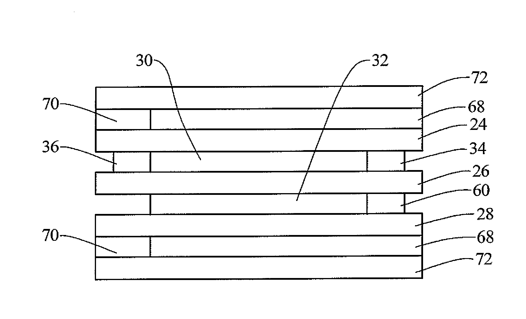
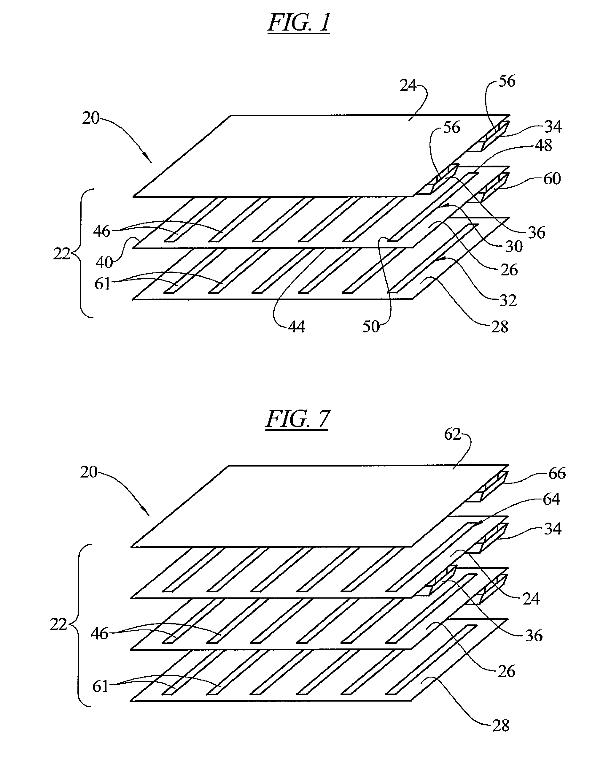
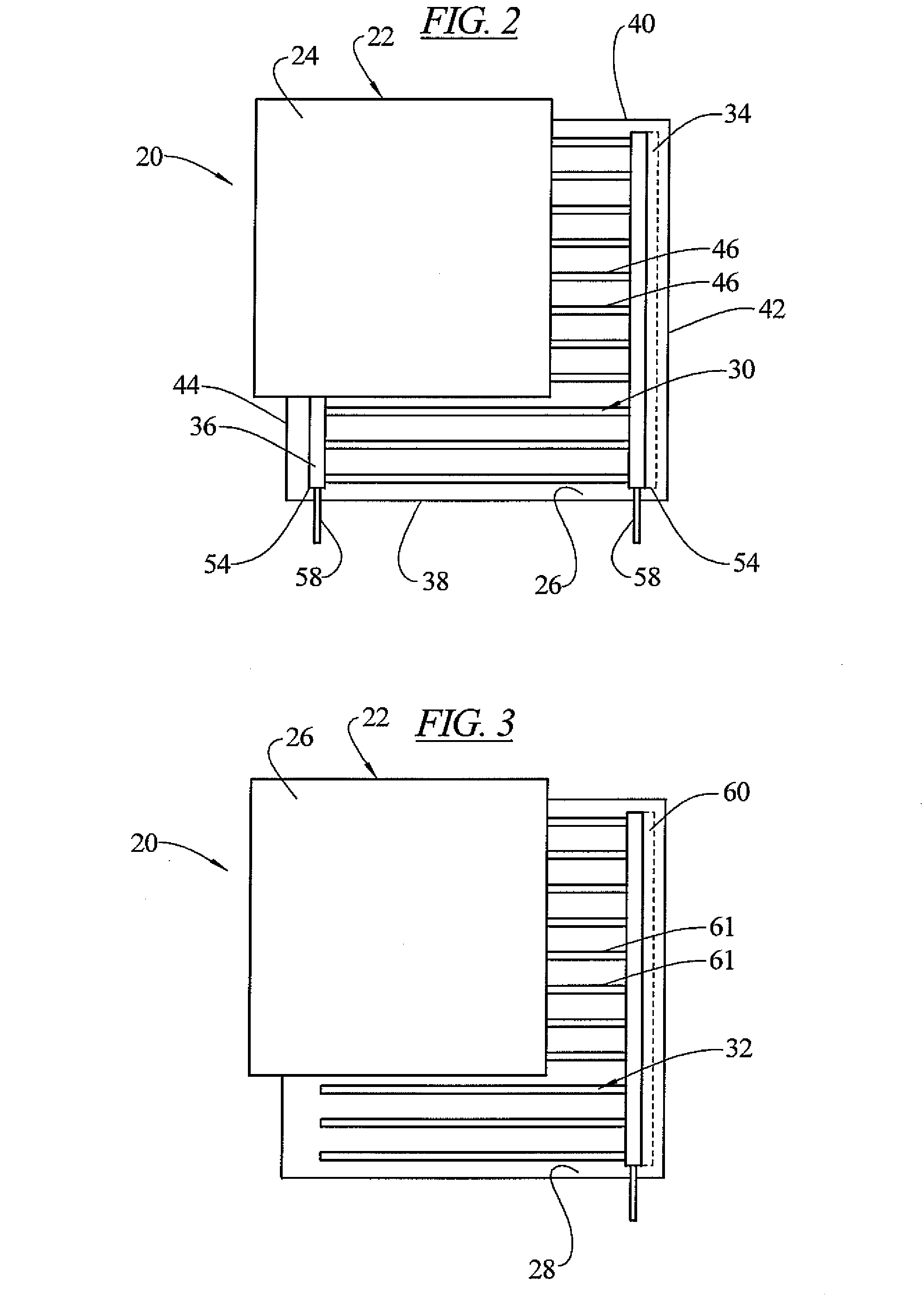
[0052]In an embodiment of the invention, as illustrated in FIGS. 1-4, a heating system 20 is provided in the form of a multi-layer, yet thin and flexible panel 22. The panel 22 contains a number of layers including first 24, second 26 and third 28 electrically insulating layers. These insulating layers are preferably formed of a polymer such as polyester, polypropylene, polyethylene, nylon or other polymers having a low dielectric constant. A first electrically conductive resistive layer 30 is sandwiched between the first 24 and second 26 electrically insulating layers. A second electrically conductive resistive layer 32 is sandwiched between the second 26 and third 28 electrically insulating layers. The electrically conductive resistive layers 30, 32, act as electrical resistors producing heat upon the passage of electrical current.

[0053]The first electrically conductive resistive layer 30 has a first electrical connection (neutral connection) 34 and a second electrical connection ...


PUM


Abstract

A heating system in the form of a multi-layer, yet relatively thin and flexible panel. The panel contains a number of layers including first, second and third electrically insulating layers. A first electrically conductive resistive layer (heater layer) is sandwiched between the first and second insulating layers. A second electrically conductive resistive layer (resistive neutral plane layer) is sandwiched between the second and third insulating layers. The heater layer has a neutral electrical connection and a live electrical connection. The neutral and live electrical connections are electrically connected to each other at the panel only by electrically resistive material of the heater layer extending between the neutral and live electrical connections. The resistive neutral plane layer has a neutral electrical connection electrically connected with the neutral connection of the heater layer. The resistive neutral plane layer is electrically isolated from the live connection of the heater layer by the second insulating layer.

Description

[0001]This application claims priority to provisional application Ser. No. 61 / 097,323 filed Sep. 16, 2008 and 61 / 176,787 filed May 8, 2009, and incorporated herein by reference in their entireties for all purposes. Patent application entitled “Heating System” filed simultaneously herewith and including related subject matter is also incorporated herein by reference in its entirety for all purposes.FIELD OF THE INVENTION[0002]The present invention relates to heating systems, and in particular, heating systems incorporated into a multi-ply panels that are relatively thin and flexible, and can be incorporated into other objects such as floors, walls or ceilings in a construction environment, or into other non-construction objects such as mirrors, picture frames, etc.BACKGROUND OF THE INVENTION[0003]Thin heating systems are known. Woven wire mesh heaters having no buses are made whereby thin wires are woven into a mesh mat. The mat can be placed under a laminate floor or under a subfloo...

Claims


Application Information

Patent Timeline
Patent Type & Authority Patents(United States)
IPC IPC(8): H05B1/00H01C1/00
CPCH05B3/34H05B2203/003H05B2203/005H05B2203/007H05B2203/009H05B2203/01H05B2203/011H05B2203/013H05B2203/026H05B3/20H05B3/84
Inventor DUBEY, ASHISH
Owner UNITED STATES GYPSUM CO
Why Eureka
Try Eureka