Check patentability & draft patents in minutes with Patsnap Eureka AI!

Device and method for the analysis of a measured signal transmitted via a multi-channel system

Active Publication Date: 2011-10-18
ROHDE & SCHWARZ GMBH & CO KG
View PDF13 Cites 1 Cited by
  • Summary
  • Abstract
  • Description
  • Claims
  • Application Information

AI Technical Summary

Benefits of technology

[0007]Embodiments of the present invention advantageously provide a device and a method for the analysis of a measured signal transmitted via a multi-channel system, wherein the measured signal is conditioned for the implementation of the analysis at a particularly low technical cost and at a particularly high speed.
[0010]The advantages achieved with the invention consist, in particular, in that the measured-signal analysis and / or modulation analysis can be implemented more rapidly by means of the device according to the invention and the method according to the invention, because the sampled measured signal is provided at the end of all measurement channels at the same time. Moreover, a particularly good measurement accuracy can be achieved with the method according to the invention. Furthermore, a bandwidth and recording length available in the measurement device, in particular a multi-channel oscilloscope, is effectively utilized. No further hardware is required in addition to the measurement device, because the outputs of the multi-channel system designed, in particular, as a MIMO system can be coupled directly to the measurement channels of the measuring device. Moreover, the purchasing cost for a measuring device comprising several measurement channels is particularly low by comparison with the purchasing cost for cascaded measuring devices each comprising only one measurement channel.

Problems solved by technology

Moreover, the purchasing cost for a measuring device comprising several measurement channels is particularly low by comparison with the purchasing cost for cascaded measuring devices each comprising only one measurement channel.

Method used


Image

  • Device and method for the analysis of a measured signal transmitted via a multi-channel system
  • Device and method for the analysis of a measured signal transmitted via a multi-channel system
  • Device and method for the analysis of a measured signal transmitted via a multi-channel system

Examples


Embodiment Construction

[0022]Corresponding components are provided with identical reference symbols in all the drawings.

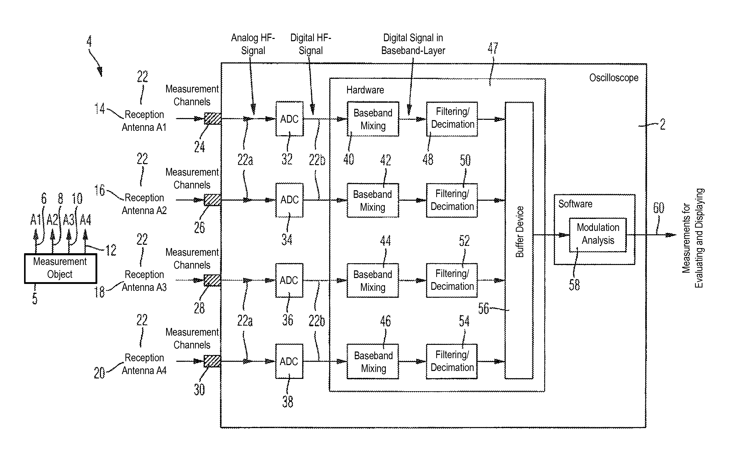
[0023]FIG. 1 shows a schematic circuit diagram of a device designed as an oscilloscope 2, which is connected to a multi-channel system 4. The multi-channel system 4 in the exemplary embodiment is a MIMO system (multiple-input multiple-output system) and comprises, for example, four transmission antennas 6, 8, 10, 12 disposed on a device under test 5 and four reception antennas 14, 16, 18, 20, across which an analog, high-frequency measured signal 22 is transmitted wirelessly from the transmission antennas 6, 8, 10, 12 to the reception antennas 14, 16, 18, 20.

[0024]At the input end, the oscilloscope 2 comprises four measurement channels 24, 26, 28, 30, the number of which corresponds with the number of reception antennas 14, 16, 18, 20 of the multi-channel system 4. Furthermore, for each measurement channel 24, 26, 28, 30, the oscilloscope 2 provides in each case one sampling device 32, 3...


PUM


Abstract

A device, in particular, a multi-channel oscilloscope, for the analysis of at least one measured signal transmitted via a multi-channel system, with several measurement channels. The device includes in each case a sampling device, a baseband mixing device, and a filter device, and an analysis device. The measured signal is supplied to the measurement channels and to the respective sampling devices for simultaneous sampling. The sampled measured signal is supplied to the baseband mixing devices connected downstream of the sampling devices for the mixing of the measured signal down into the baseband, to the filter devices connected downstream of the baseband mixing devices for the decimation of the sampled values of the measured signal in the baseband and to the analysis device connected to the filter devices for the analysis of the measured signal.

Description

CROSS-REFERENCE TO RELATED APPLICATION[0001]The present application claims priority to PCT Application No. PCT / EP2007 / 006102, filed on Jul. 10, 2007, and German Patent Application No. 10 2006 042 114.0, filed on Sep. 7, 2006, the entire contents of which are herein incorporated by reference.BACKGROUND OF THE INVENTION[0002]1. Field of the Invention[0003]The invention relates to a device, in particular, a multi-channel oscilloscope, and to a method for the analysis of a measured signal transmitted via a multi-channel system.[0004]2. Discussion of the Background[0005]In communications technology, a multi-channel system is used for the transmission of signals, in order to increase the data rate per bandwidth used and to reduce the bit-error rate. A multi-channel system can be used, for example, in a wireless communications system, which provides a so-called single-input multiple-output (SIMO) system via one transmission antenna and several reception antennas, or a so-called multiple-in...

Claims


Application Information

Patent Timeline
IPC IPC(8): G01R23/14
CPCG01R13/0254
Inventor KUHWALD, THOMASFREIDHOF, MARKUS
Owner ROHDE & SCHWARZ GMBH & CO KG
Features
  • R&D
  • Intellectual Property
  • Life Sciences
  • Materials
  • Tech Scout
  • Unparalleled Data Quality
  • Higher Quality Content
  • 60% Fewer Hallucinations
Learn More