Position sensor system for substrate transfer robot

a technology of substrate transfer robot and sensor system, which is applied in the field of substrate processing, can solve problems such as damage to the substrate, non-uniform process, and substrate dri

Active Publication Date: 2011-10-18
ASM JAPAN
View PDF83 Cites 390 Cited by
  • Summary
  • Abstract
  • Description
  • Claims
  • Application Information

AI Technical Summary

Problems solved by technology

This can cause non-uniformity in process results, as most semiconductor processing depends critically on temperature.
Substrate drift can also occur during robot movement, particularly when the robot moves fast.
In addition to the aforementioned problems associated with failing to center the substrate within a susceptor pocket, substrate drift can result in damage to the substrate during placement at a substrate station, such as a wafer cassette.

Method used


Image

  • Position sensor system for substrate transfer robot
  • Position sensor system for substrate transfer robot
  • Position sensor system for substrate transfer robot

Examples


Embodiment Construction

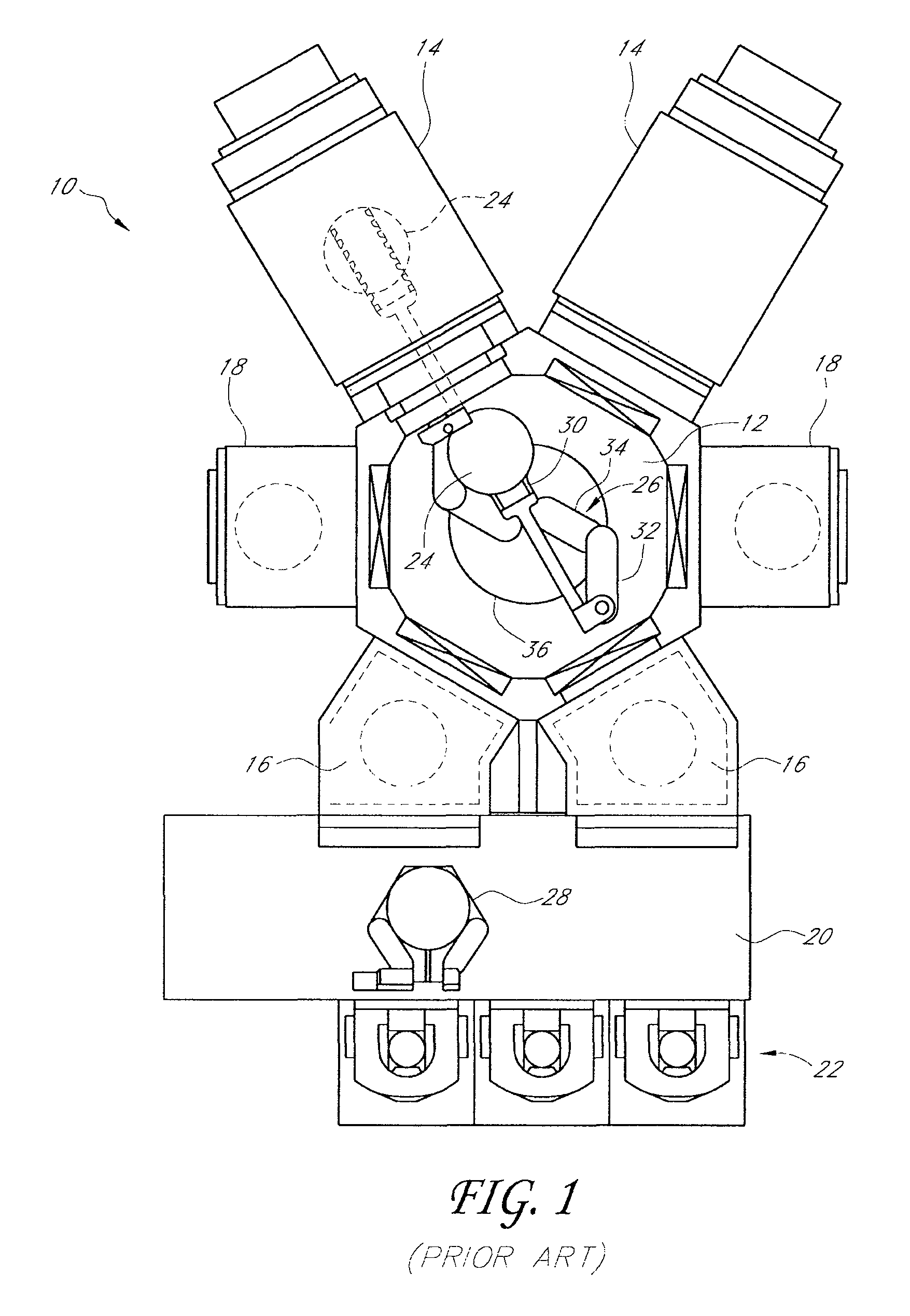
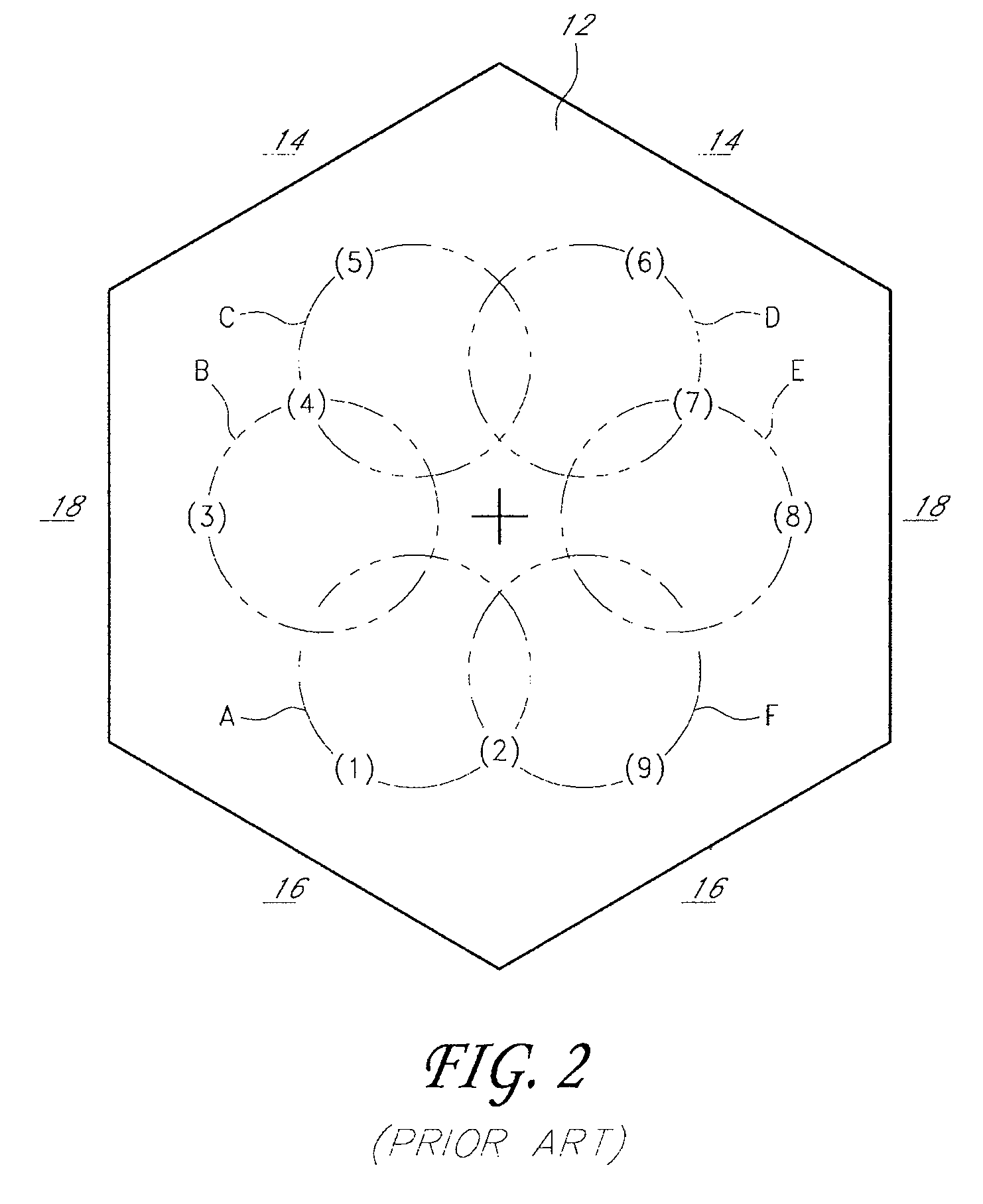
[0028]One problem with the above-described conventional methods of detecting substrate drift is that the robot arms sometimes interfere with the light beams emitted by the photosensors, which prevents detection of the substrate position. Each photosensor typically includes a light beam emitter above the end effector and oriented to emit a beam of light downwardly, and a light beam receiver below the end effector and configured to receive the beam of light from the emitter. The robot arms, in certain positions, can block the light beams and thereby interfere with the sensors' ability to sense the substrate position. Also, in apparatuses having multiple robots holding multiple substrates simultaneously, the substrates often overlap each other, and sometimes it is not possible to determine which substrate is being detected. Further, in some cases a photosensor's light beam is impeded by two different substrates, which results in a distorted calculation of the targeted substrate's posit...


PUM


Abstract

A substrate processing apparatus comprises a substrate handling chamber, a pair of position sensors, and a substrate transfer robot. Each of the sensors comprises an emitter configured to emit a beam of light, and a receiver configured to receive the light beam. The substrate transfer robot comprises an end effector and a robot actuator. The end effector is configured to hold a substrate such that the substrate has a same expected position with respect to the end effector every time the substrate is held. The robot actuator is configured to move the end effector within the handling chamber to transfer substrates among a plurality of substrate stations. An edge of a substrate held in the expected position by the end effector can partially block a light beam of one of the position sensors, while another end of the end effector partially blocks a light beam of the other position sensor.

Description

BACKGROUND[0001]1. Field[0002]The present application relates generally to substrate processing and, more particularly, to methods and apparatuses for transferring substrates through a substrate processing system.[0003]2. Description of the Related Art[0004]An apparatus for processing semiconductor substrates, such as silicon wafers, typically includes a processing chamber in which the substrates are processed, a substrate handling chamber through which the substrates are moved before and after processing in the processing chamber, and one or more input / output chambers that store substrates before and after the substrates are moved through the handling chamber. A substrate transfer robot is located within the handling chamber and is configured to transfer substrates to and from a plurality of stations. Such stations may be within the handling chamber, the input / output chambers, the processing chamber, or other chambers. A typical station within the processing chamber is a substrate ...

Claims


Application Information

Patent Timeline
Patent Type & Authority Patents(United States)
IPC IPC(8): G06F19/00G05B15/02
CPCH01L21/68707H01L21/67265B25J11/0095B25J19/021H01L21/67742H01L21/681Y10S414/141
Inventor TAKIZAWA, MASAHIROSUWADA, MASAEI
Owner ASM JAPAN
Why Eureka
Try Eureka