Substrate treatment apparatus

a substrate treatment and substrate technology, applied in the direction of electrical equipment, thin material processing, article separation, etc., can solve the problems of increasing the occupied floor area of the coating/developing apparatus, the cassette cannot be loaded on the cassette loading table, etc., to achieve the effect of not without increasing the occupied floor area, and without lowering the throughput of the substrate treatment apparatus

Inactive Publication Date: 2011-10-25
TOKYO ELECTRON LTD
View PDF9 Cites 9 Cited by
  • Summary
  • Abstract
  • Description
  • Claims
  • Application Information

AI Technical Summary

Benefits of technology

[0012]According to the aspect of the present invention, the vacant cassette from which the substrate is carried out can be temporarily loaded on the vacant cassette loading portion from the cassette loading portion. Accordingly, additional cassettes can be sequentially carried in the cassette loading portion, so substrates can be sequentially carried in the substrate treatment portion without time intervals even in a small-lot treatment in which the number of substrates in one cassette is small. As a result, it is possible to deal with the small-lot treatment without lowering a throughput in the substrate treatment apparatus. Further, it is also possible to deal with the small-lot treatment without increasing an occupied floor area of the substrate treatment apparatus. According to the present invention, it is possible to deal with the small-lot treatment without lowering the throughput of the substrate treatment apparatus and without increasing the occupied floor area.

Problems solved by technology

However, the cassette stands by on the cassette loading table until the wafers are returned from the treatment station, so an additional cassette cannot be loaded on the cassette loading table, although there is an open space for the wafer treatment in the treatment station.
However, this results in an increase in occupied floor area of the coating / developing apparatus, and requires a structure of the cassette station to be significantly changed.

Method used


Image

  • Substrate treatment apparatus
  • Substrate treatment apparatus
  • Substrate treatment apparatus

Examples


Embodiment Construction

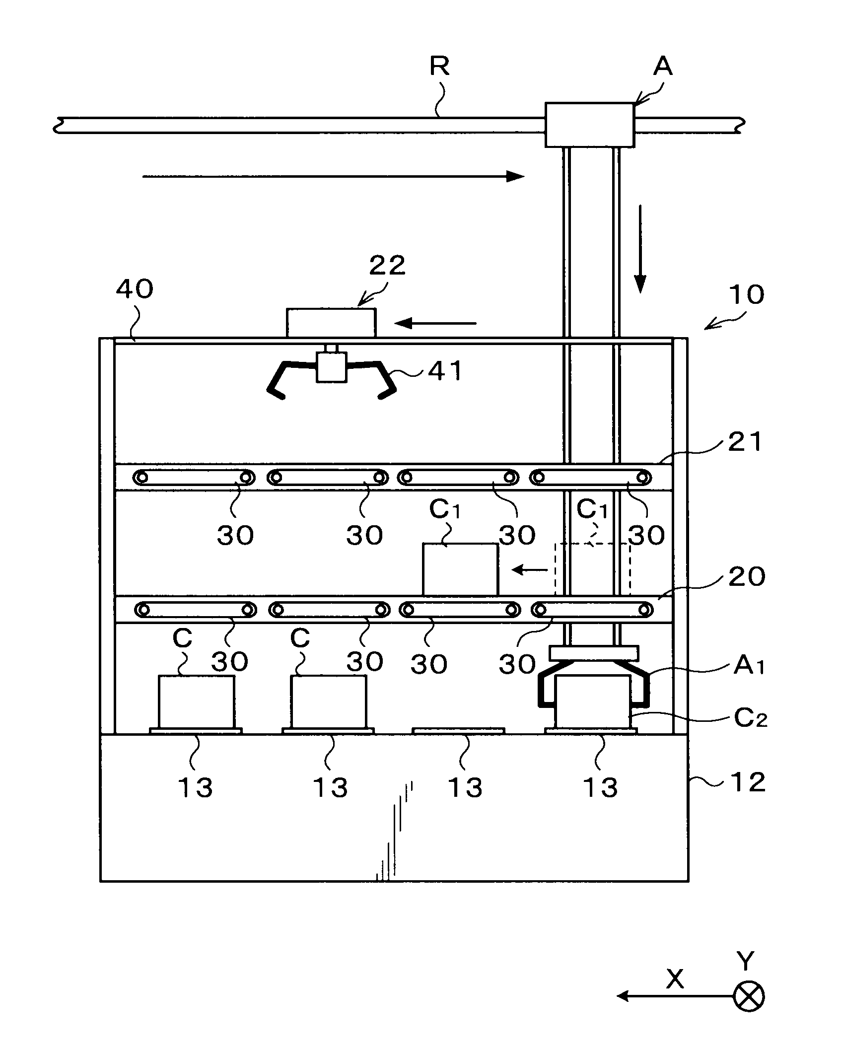
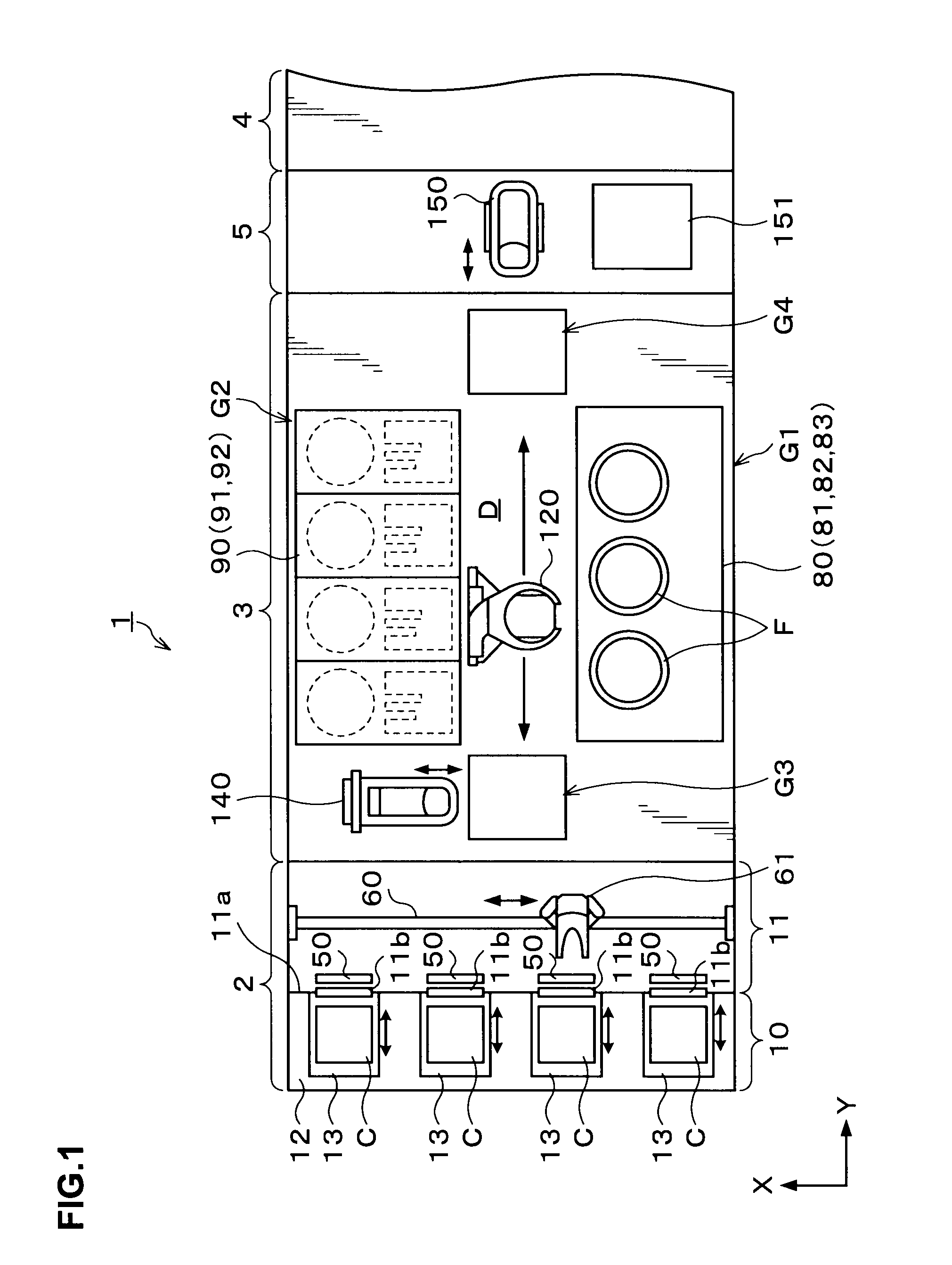
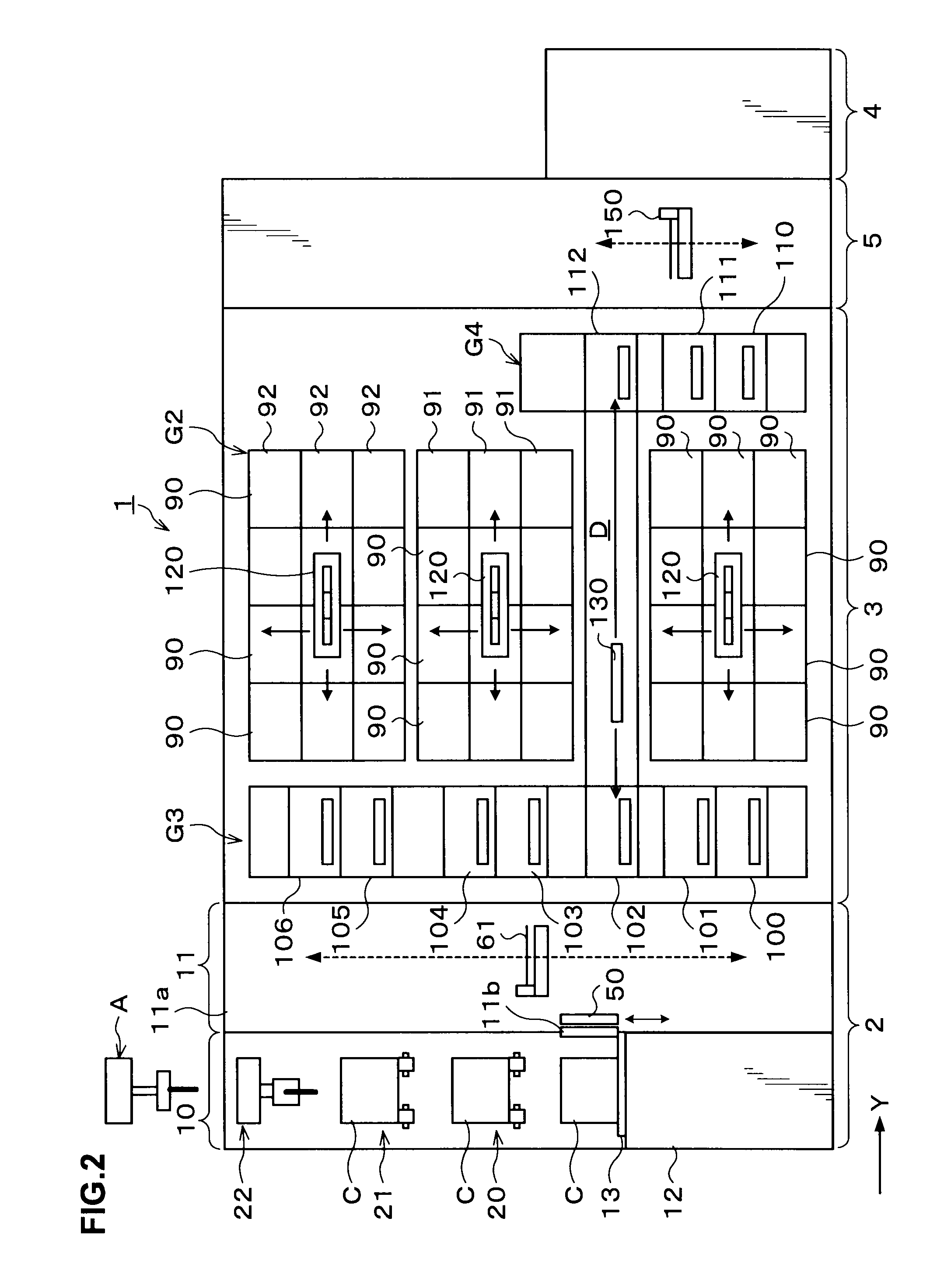
[0041]Hereinafter, embodiments of the present invention will be described. FIG. 1 is an explanatory view schematically showing an inner structure of a coating / developing apparatus 1 as a substrate treatment apparatus according to the present invention. FIGS. 2 and 3 are side views each schematically showing the inner structure of the coating / developing apparatus 1.

[0042]As shown in FIG. 1, the coating / developing apparatus 1 has a structure in which a cassette station 2, a treatment station 3, and an interface station 5 are integrally connected to each other. A cassette C is carried to / from the cassette station 2 from / to outside. The treatment station 3 serves as a substrate treatment portion including a plurality of various kinds of treatment units that perform predetermined treatments in a sheet-feed manner in a photolithography. Through the interface station 5 adjacent to the treatment station 3, a wafer W is carried to / received from an exposing apparatus 4.

[0043]The cassette stat...


PUM


Abstract

A substrate treatment apparatus is disclosed. The substrate treatment apparatus includes: a cassette loading portion on which a cassette for containing a substrate is loaded when the cassette is carried to / from outside of the substrate treatment apparatus; a substrate treatment portion for performing a treatment on the substrate; a substrate carrying portion for carrying the substrate in the cassette loaded on the cassette loading portion to the substrate treatment portion, and carrying the substrate that has been subjected to the treatment by the substrate treatment portion to the cassette on the cassette loading portion; a vacant cassette loading portion on which the cassette caused to be vacant by carrying the substrate to the substrate treatment portion is temporarily loaded; and a vacant cassette transfer mechanism for transferring the vacant cassette between the vacant cassette loading portion and the cassette loading portion.

Description

BACKGROUND OF THE INVENTION[0001]1. Field of the Invention[0002]The present invention relates to a substrate treatment apparatus for performing treatment on a substrate.[0003]2. Description of the Related Art[0004]In a photolithography process in a manufacturing process of a semiconductor device, a series of treatments including a resist coating treatment, an exposing treatment, and a developing treatment are performed, for example. In the resist coating treatment, a resist solution is applied to a wafer to form a resist film. In the exposing treatment, the resist film is exposed to have a predetermined circuit pattern. In the developing treatment, the exposed resist film is developed. Thus, a predetermined resist pattern is formed on the wafer. The series of treatments are performed in a coating / developing apparatus to which various kinds of treatment units for performing treatments on a wafer, a carrying apparatus for carrying the wafer, and the like are provided.[0005]Generally, ...

Claims


Application Information

Patent Timeline
Patent Type & Authority Patents(United States)
IPC IPC(8): H01L21/677
CPCH01L21/67766H01L21/67775Y10S414/14
Inventor YAMAMOTO, YUICHITERAMOTO, AKIHIROTSUKINOKI, WATARU
Owner TOKYO ELECTRON LTD
Why Eureka
Try Eureka