Manhole cover lifting apparatus and method

a manhole cover and lifting apparatus technology, applied in the field of manhole cover lifting apparatus and method, can solve the problems of high risk operation of removing and replacing manhole covers, back and other muscular-skeletal injuries, etc., and achieve the effect of reducing or eliminating

Inactive Publication Date: 2011-10-25
NEELEY ALVIN L +1
View PDF15 Cites 12 Cited by
  • Summary
  • Abstract
  • Description
  • Claims
  • Application Information

AI Technical Summary

Benefits of technology

[0018]The lifting assembly of the present invention is arranged to lift an object which has a width dimension and it at least partially surrounded by a base surface which has a substantial horizontal alignment component. In the preferred embodiment, this object is a manhole cover (also called a vault cover) surrounded by a paved or ground surface. This lifting assembly is particularly adapted to enable the object (or manhole cover) to be lifted in a manner which substantially eliminates, or at least substantially alleviates, potential injury to a workman who is to remove the manhole cover.

Problems solved by technology

Statistically, the task of removing and replacing manhole covers has been found to be a high risk operation in terms of promoting and or causing back and other muscular-skeletal injuries.

Method used


Image

  • Manhole cover lifting apparatus and method
  • Manhole cover lifting apparatus and method
  • Manhole cover lifting apparatus and method

Examples


Embodiment Construction

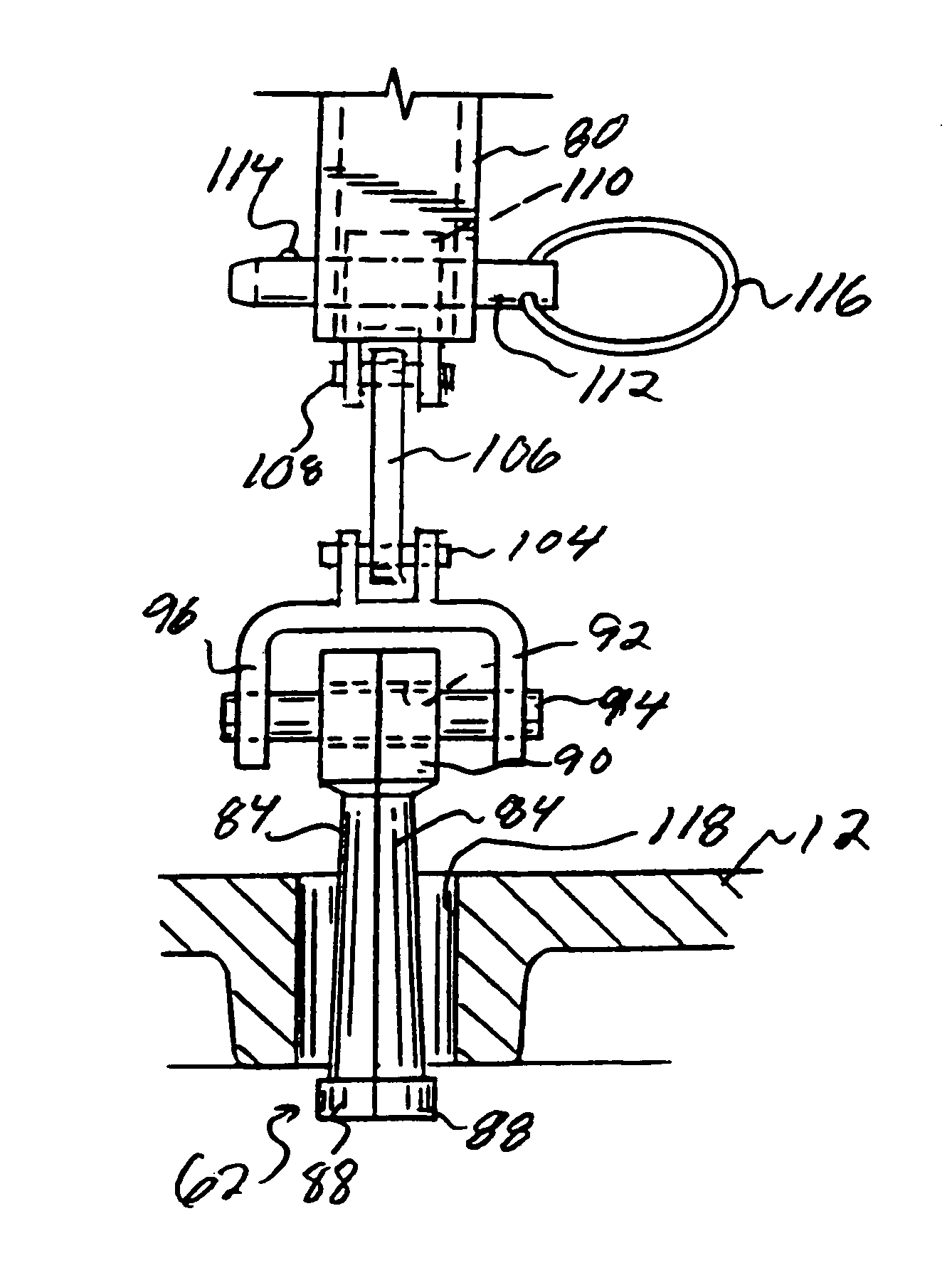
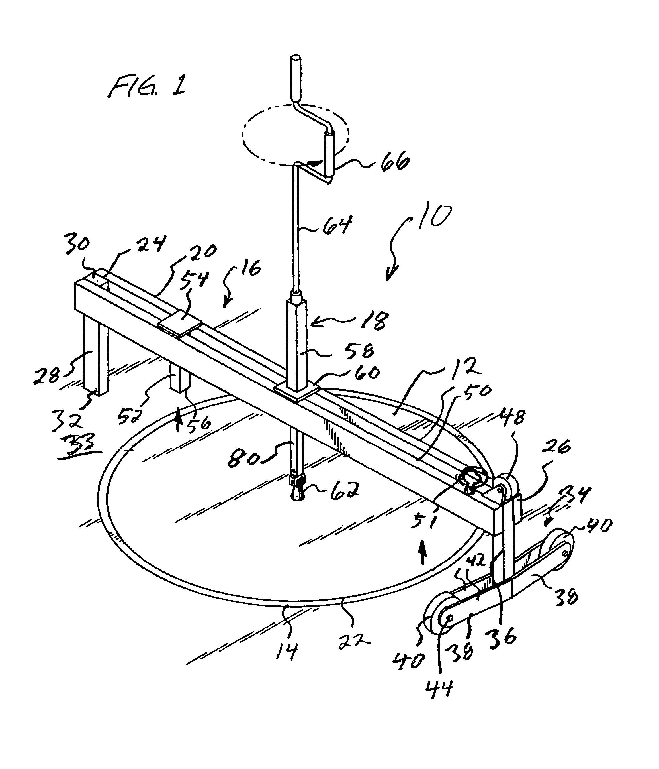
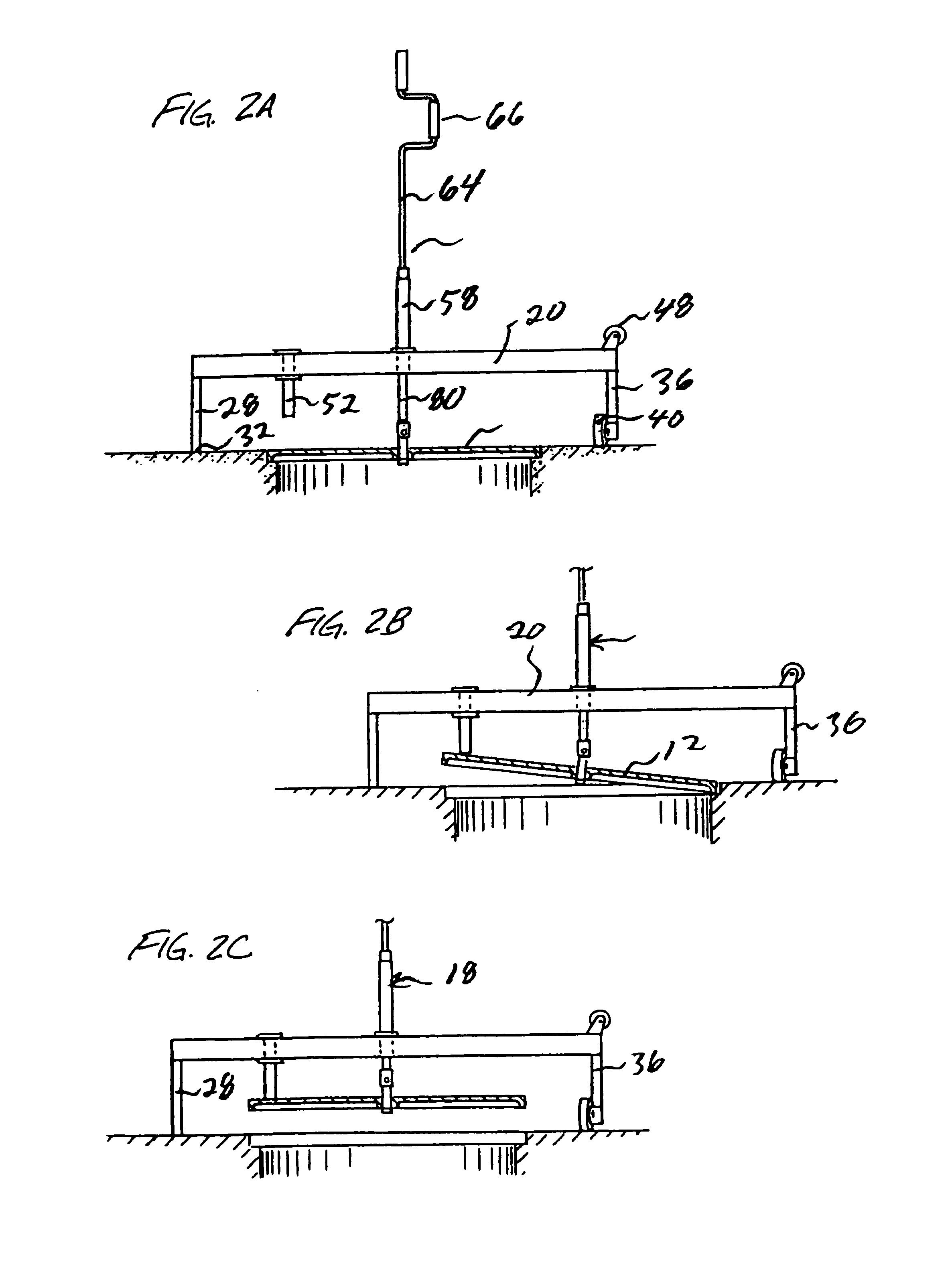
[0048]The apparatus 10 of the present invention is shown in FIG. 1 in its operating position to lift a manhole cover 12 out of its surrounding support frame 14. More recently a “manhole cover” is often referred to as a “vault cover” or a “utility vault cover”. It is to be understood that the term “manhole cover” also refers to these. This apparatus 10 comprises two main components, namely a lift support base assembly 16 and a lifting mechanism 18.

[0049]The base assembly 16 comprises three main components. First, there is a main lifting bar 20 which in the operating position of FIG. 1 extends entirely across the manhole cover 12 so that both ends of the bar 20 extend beyond the perimeter 22 of the manhole cover 12. This bar 20 has a pivot end 24 and a mobile end 26. This bar functions as a beam structure and could also be configured as a truss or other support member to transfer lifting loads from a central location out to the end locations.

[0050]The second component of the base asse...


PUM


Abstract

A manhole lifting apparatus comprising a base support assembly and a lifting mechanism. There is a beam structure which extends over the manhole, with a pivot support at one end of the beam structure, and a mobile support at the opposite end of the beam structure. The lifting mechanism is at the central part of the beam structure. The lifting mechanism lifts the manhole cover, and the support assembly is rotated about the pivot support to remove the manhole cover from the manhole.

Description

RELATED APPLICATIONS[0001]This Patent Application is a continuation of U.S. Ser. No. 09 / 233,417 filed Jan. 19, 1999 (now abandoned), which is a continuation of U.S. Ser. No. 08 / 625,698 filed Apr. 3, 1996 (now abandoned), which is a continuation of Ser. No. 08 / 489,360 filed Jun. 12, 1995 (now abandoned).BACKGROUND OF THE INVENTION[0002]a) Field of the Invention[0003]The present invention relates to an apparatus and method for lifting and removing larger and heavier objects which are at least moderately awkward to handle, and more particularly to such an apparatus and method for lifting and removing manhole covers from a manhole frame, and accomplishing this in a manner to facilitate the process to avoid injury to workers.[0004]b) Background Art[0005]Manholes are commonly located at streets and other surface locations to provide access to some underground location, and these are commonly used in connection with utilities (power or communication lines, sewers, etc.). When a workman tra...

Claims


Application Information

Patent Timeline
Patent Type & Authority Patents(United States)
IPC IPC(8): B66C11/12B66F3/08B66F11/00E02D29/12
CPCE02D29/1445B66F19/005
Inventor NEELEY, ALVIN L.DAVIS, STEVEN M.
Owner NEELEY ALVIN L
Why Eureka
Try Eureka