Noise suppressing damper

a technology of damper and air conditioner, which is applied in the direction of ventilation system, heating type, domestic cooling apparatus, etc., can solve the problems of air noise likely to be caused, the technique may fail to suppress the generation of air noise, etc., and achieve the effect of suppressing air noise, suppressing air noise, and suppressing air nois

Inactive Publication Date: 2011-10-25
MITSUBISHI HEAVY IND LTD
View PDF18 Cites 16 Cited by
  • Summary
  • Abstract
  • Description
  • Claims
  • Application Information

AI Technical Summary

Benefits of technology

[0009]In consideration with the aforementioned disadvantage, it is an object of the present invention to provide the damper, the air conditioning unit, and the vehicular air conditioning system capable of suppressing the abnormal noise (air noise) at the small opening of the damper.
[0037]In the vehicular air conditioning system according to the fifth aspect, which is provided with the damper according to any one of the first to the third aspect, and the air conditioning unit according to the fourth aspect, the side expanded portion is formed as the protruding convex curve surface. This makes it possible to form the stable accelerated air flow between the one end and the stationary portion, and to suppress the air noise generated at the small opening of the damper.

Problems solved by technology

However, the proposed technique may fail to suppress generation of the air noise because of the complicated shape of the flow passage in the vehicular air conditioning system.
The air noise is likely to be caused by the influence of the shape of the flow passage upstream or downstream of the region where the cross-section area of the flow passage is reduced.

Method used


Image

  • Noise suppressing damper
  • Noise suppressing damper
  • Noise suppressing damper

Examples


first embodiment

[0065]A vehicular air conditioning system according to a first embodiment of the present invention will be described referring to FIGS. 1 to 7.

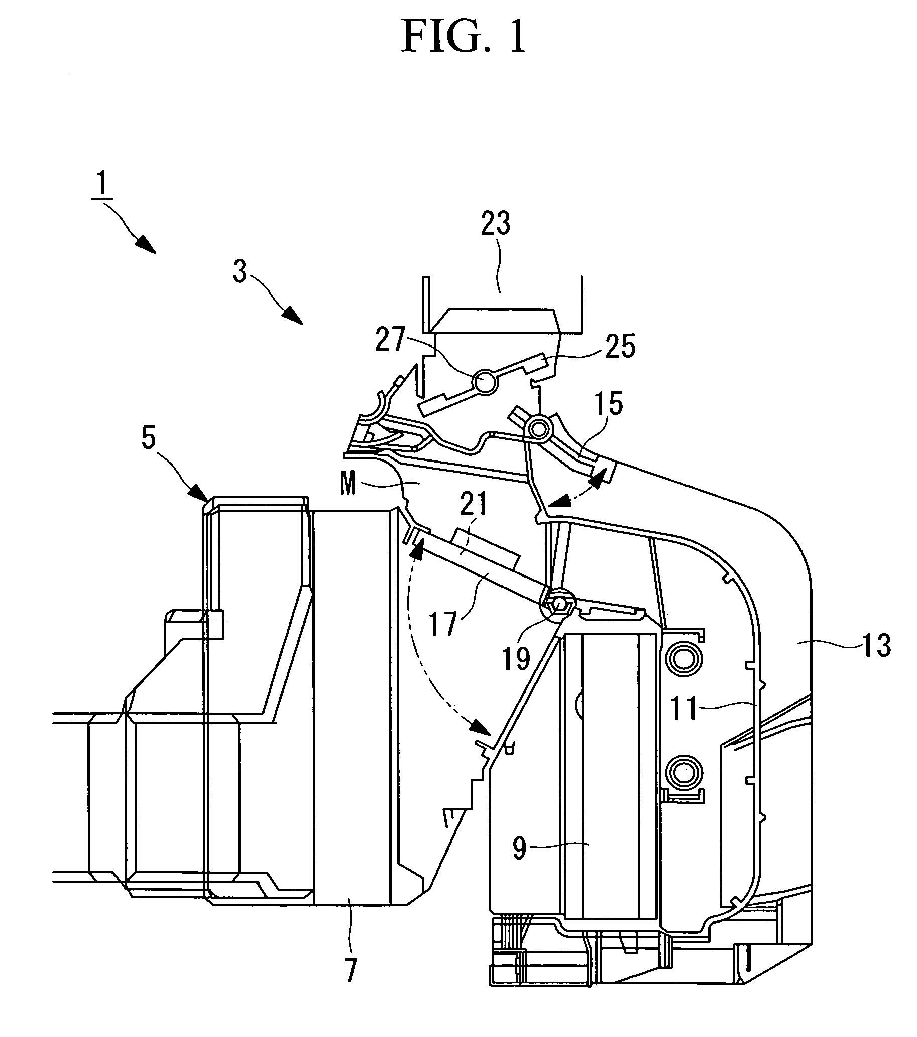
[0066]FIG. 1 is a sectional view illustrating an outline structure of an HVAC unit of the vehicular air conditioning system according to the embodiment.

[0067]The HVAC (Heating, Ventilation, and Air-Conditioning) unit (air conditioning unit) 3 in the vehicular air conditioning system 1 includes a casing 5, an evaporator 7, and a heater core 9 as shown in FIG. 1.

[0068]The vehicular air conditioning system 1 supplies conditioned air to the vehicle interior for heating and dehumidification to make the interior environment comfortable. The vehicular air conditioning system 1 includes a closed circuit refrigerating cycle formed by connecting a compressor (not shown) operated by a part of the output of the internal combustion engine for the vehicle, a condenser (not shown) for condensing the gas refrigerant through heat exchange with the outdoor air...

second embodiment

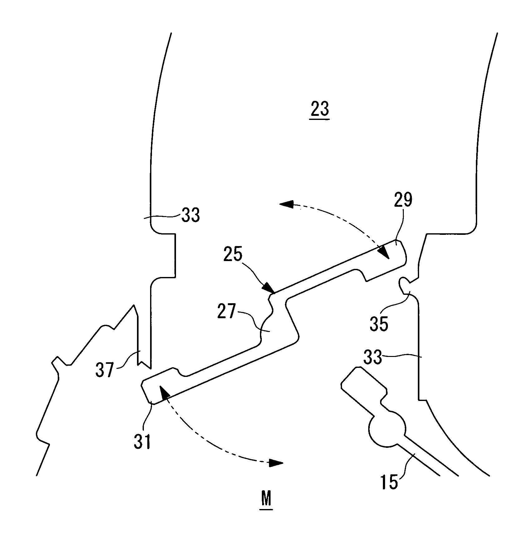
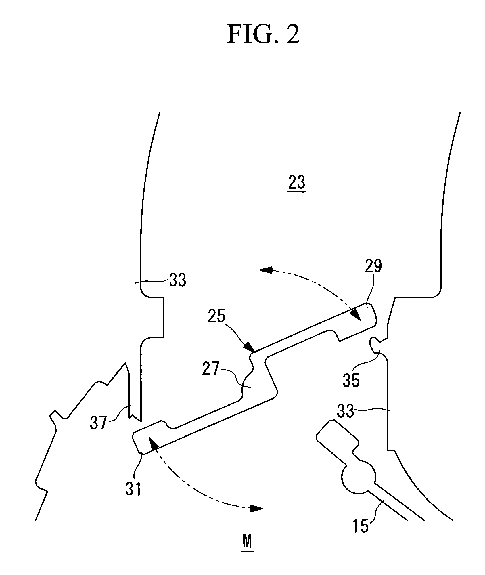
[0114]A second embodiment according to the present invention will be described referring to FIGS. 8 and 9.

[0115]The basic structure of the vehicular air conditioning system of the embodiment is substantially the same as that of the first embodiment except the structure of the leading end of the air-mix damper. Accordingly, the structure of the leading end of the air-mix damper will only be described referring to FIGS. 8 and 9, and the explanation of the other elements will be omitted.

[0116]FIG. 8 is a sectional view partially showing the structure of the leading end of the air-mix damper in the embodiment. FIG. 9 is a sectional view partially representing the positional relationship between the leading end shown in FIG. 8 and the air-mix rib portion.

[0117]The same elements as those in the first embodiment will be designated with the same reference numerals, and explanations thereof, thus will be omitted.

[0118]A leading end (one end) 155 of the edge member 53 of the air-mix damper 17...


PUM


Abstract

A damper is provided to suppress the abnormal noise or air noise at the small opening of the damper. The damper includes a wall surface which forms an air flow passage, a stationary portion which extends from the wall surface to the center of a flow passage, and a rotating portion rotatably disposed in the flow passage, having one end in contact with a portion of the stationary portion at a downstream side of an air flow through the flow passage. A curved wall portion as a convex curved surface protruding to the center of the flow passage is formed on a position of the wall surface on which the air flow passing between the one end and the stationary portion impinges.

Description

TECHNICAL FIELD[0001]The present invention relates to a damper, an air conditioning unit, and a vehicular air conditioning system.BACKGROUND ART[0002]Generally, a vehicular air conditioning system controls a flow direction of conditioned air through a flow passage inside the system, a flow rate of the conditioned air to supply the conditioned air at different temperatures to a plurality of regions of a vehicle interior such that the atmospheric temperatures of the respective regions may be individually controlled. The damper which is opened and closed to control the cross-section area of the flow passage has been employed for controlling the flow direction and the flow rate of the conditioned air.[0003]Under the control of the flow direction or flow rate of the conditioned air using the damper as described above, it is well known that the abnormal noise (air noise or wind noise; hereinafter referred to as the air noise) is heard when the conditioned air passes the region with the re...

Claims


Application Information

Patent Timeline
Patent Type & Authority Patents(United States)
IPC IPC(8): F24F13/14F24F13/10F24F13/04
CPCB60H1/00671F24F13/1406B60H2001/00714B60H2001/006
Inventor EGUCHI, TSUYOSHISUZUKI, ATSUSHITOMINAGA, TETSUONAKAO, MITSUHIROIZUMI, HAJIMEITO, JUNKOMINAMI, SATOSHI
Owner MITSUBISHI HEAVY IND LTD
Why Eureka
Try Eureka