Wear leveling method and controller using the same
a leveling method and controller technology, applied in the field of wear leveling method, can solve the problems of flash memory storage capacity or performance degradation, data loss, flash memory block can be erased only a limited extent, etc., and achieve the effect of prolonging the life of non-volatile memory
- Summary
- Abstract
- Description
- Claims
- Application Information
AI Technical Summary
Benefits of technology
Problems solved by technology
Method used
Image
Examples
first embodiment
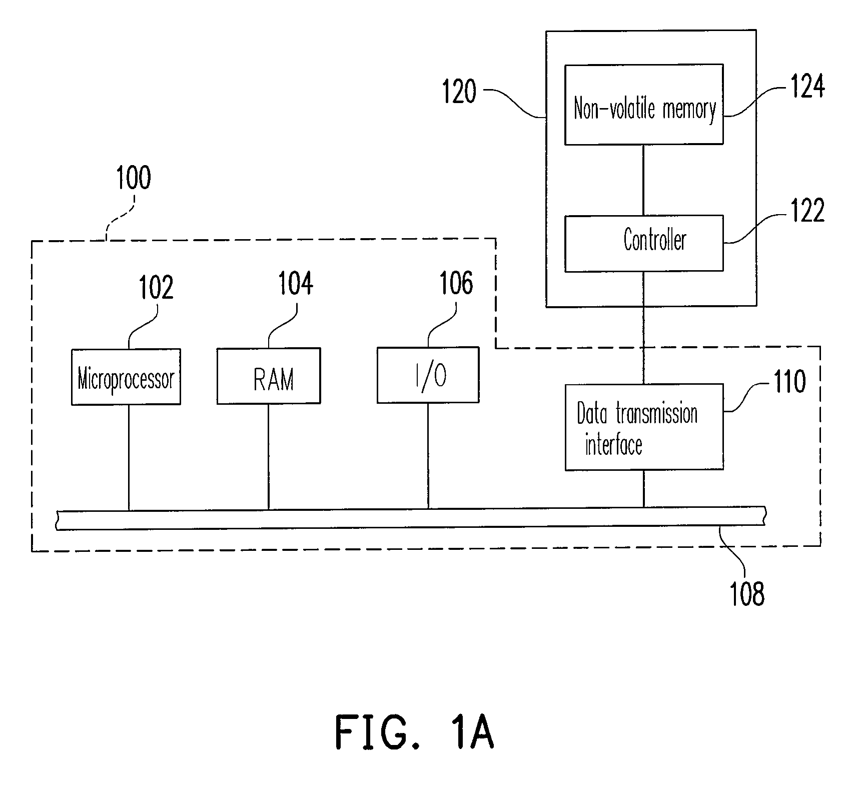
[0035]FIG. 1A illustrates a host having a non-volatile memory storage device according to the first embodiment of the present invention.
[0036]Referring to FIG. 1A, the host 100 includes a microprocessor 102, a random access memory (RAM) 104, an input / output (I / O) device 106, a system bus 108, and a data transmission interface 110. It should be noted that the host 100 may further include other components, such as a display or a network device.
[0037]The host 100 may be a computer, a digital camera, a video camera, a communication device, an audio player, or a video player. Generally speaking, the host 100 can be any system which can store data.
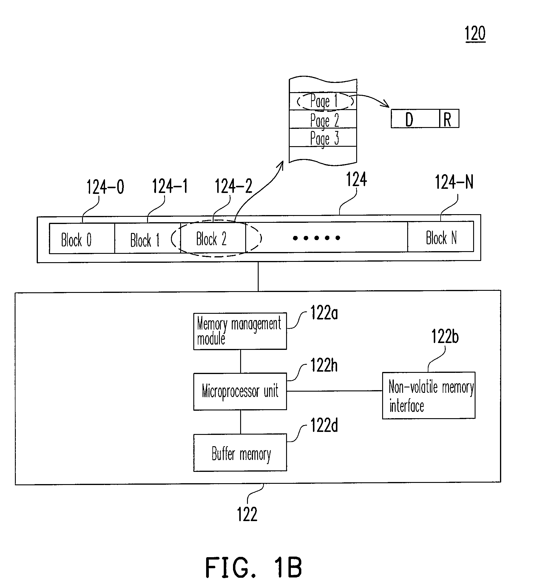
[0038]In the present embodiment, the non-volatile memory storage device 120 is electrically connected to other components of the host 100 through the data transmission interface 110. Data can be written into or read from the non-volatile memory storage device 120 through the microprocessor 102, the RAM 104, and the I / O device 106. The non-volati...
second embodiment
[0088]The hardware structure, the operation of the non-volatile memory, and the recording of the block erase counts in the second embodiment of the present invention are the same as those in the first embodiment (as shown in FIGS. 1A˜1B, 2A˜2B, and 4A˜4D) therefore will not be described herein. The difference between the second embodiment and the first embodiment is that in the second embodiment, a selection condition is specified to blocks which are to be used only in the substitute area.
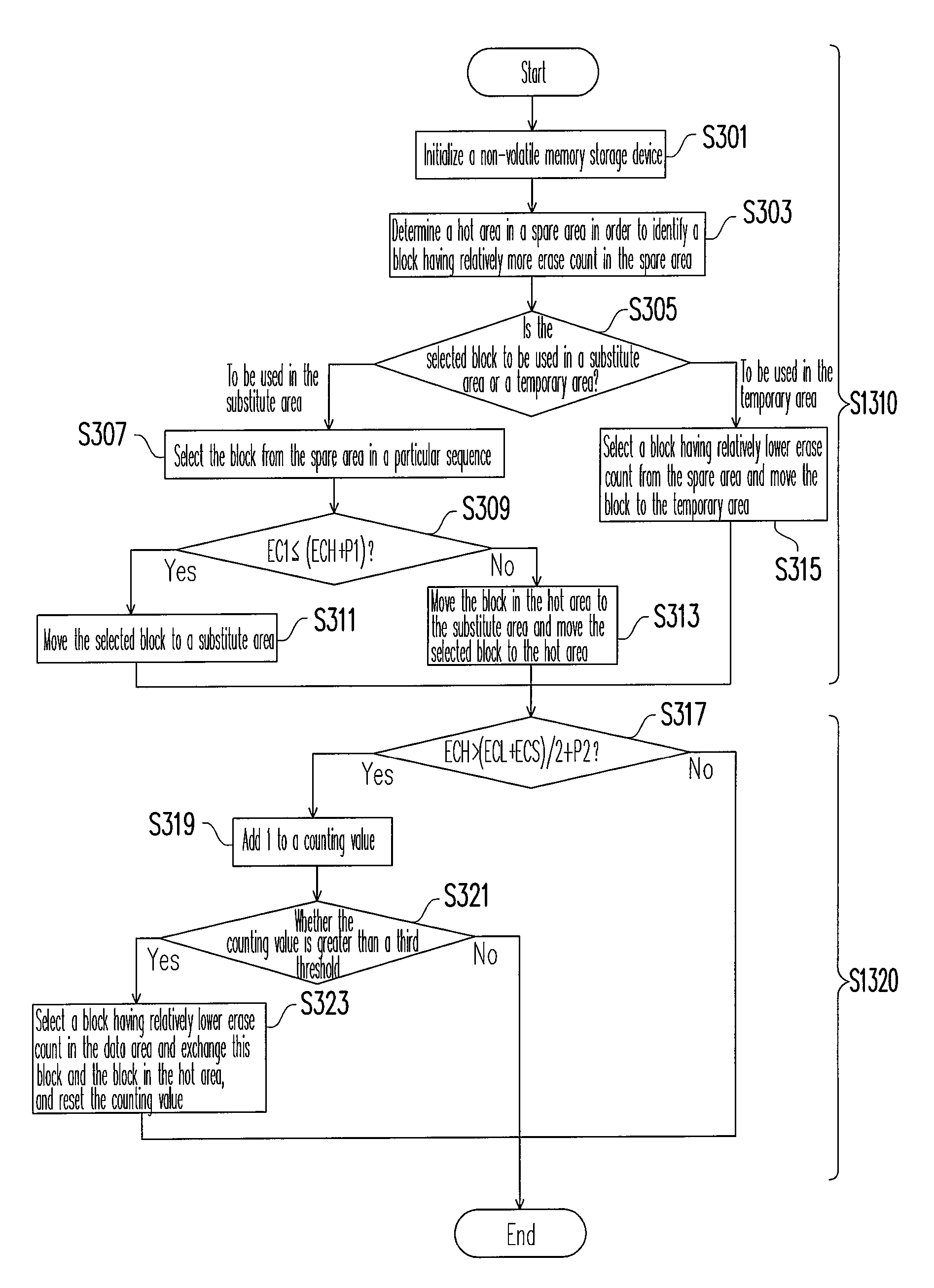
[0089]FIG. 5 is a flowchart of a wear leveling method according to the second embodiment of the present invention. Referring to FIG. 5, the difference of the flowchart illustrated in FIG. 5 from the flowchart illustrated in FIG. 3 is that in step S1310′, a selection condition is specified only to blocks which are to be used in the substitute area 208. In the second embodiment, the selection condition for selecting blocks to be used in the substitute area 208 and the other steps of the wear leveling...
third embodiment
[0090]The hardware structure, the operation of the non-volatile memory, and the recording of the block erase counts in the third embodiment of the present invention are the same as those in the first embodiment (as shown in FIGS. 1A˜1B, 2A˜2B, and 4A˜4D) therefore will not be described herein. The difference between the third embodiment and the first embodiment is that in the third embodiment, a selection condition is specified to blocks which are to be used only in the temporary area.
[0091]FIG. 6 is a flowchart of a wear leveling method according to the third embodiment of the present invention. Referring to FIG. 6, the difference of the flowchart illustrated in FIG. 6 from the flowchart illustrated in FIG. 3 is that in step S1310″, a selection condition is specified to only blocks which are to be used in the temporary area 210. In the third embodiment, the selection condition for selecting blocks to be used in the temporary area 210 and the other steps of the wear leveling method ...
PUM
 Abstract
Description
Claims
Application Information
 - R&D
- Intellectual Property
- Life Sciences
- Materials
- Tech Scout
- Unparalleled Data Quality
- Higher Quality Content
- 60% Fewer Hallucinations
Browse by: Latest US Patents, China's latest patents, Technical Efficacy Thesaurus, Application Domain, Technology Topic, Popular Technical Reports.
© 2025 PatSnap. All rights reserved.Legal|Privacy policy|Modern Slavery Act Transparency Statement|Sitemap|About US| Contact US: help@patsnap.com


