
Method and mechanism for cache compaction and bandwidth reduction

a cache and bandwidth reduction technology, applied in the field of memory systems in computer systems, can solve the problems of increasing the demands on the memory system, increasing the cost, and increasing the size of the main memory system

Active Publication Date: 2011-10-25
ORACLE INT CORP
View PDF10 Cites 14 Cited by
  • Summary
  • Abstract
  • Description
  • Claims
  • Application Information

AI Technical Summary

Problems solved by technology

However, having multiple threads in execution increases the demands on the memory system.
Generally speaking, a larger main memory system translates to increased costs.
First, the number of memory chips is increased, which clearly drives the cost up.
Second, to provide an appropriate level of performance with a larger memory size (in terms of latency and bandwidth, for example), expensive implementation techniques may be required.
Third, providing low latency, high bandwidth access to a large main memory may result in increased power consumption of the memory system (as compared to traditionally-sized memory systems).
The increased power consumption may increase cooling requirements and power supply requirements for the computer system, which may also increase cost.
In addition, while new multi-core CMT and CMP processor chips may promise a high compute bandwidth, the requirement that bandwidth in and out of the chip scale linearly with the number of cores may severely constrain future systems.
Consequently, the off-chip bandwidth may ultimately constrain CMT / CMP chips as the cache capacity on-chip will likely not be able to scale with the number of cores.
However, increasing the size of on-chip caches reduces the area which can be devoted to processing cores.
However, such approaches do not predict future accesses and do not avoid future misses.
While compression of the on-chip caches may improve performance, additional latencies may be introduced due to the decompression overhead which is required.

Method used


Image

  • Method and mechanism for cache compaction and bandwidth reduction
  • Method and mechanism for cache compaction and bandwidth reduction
  • Method and mechanism for cache compaction and bandwidth reduction

Examples


Embodiment Construction

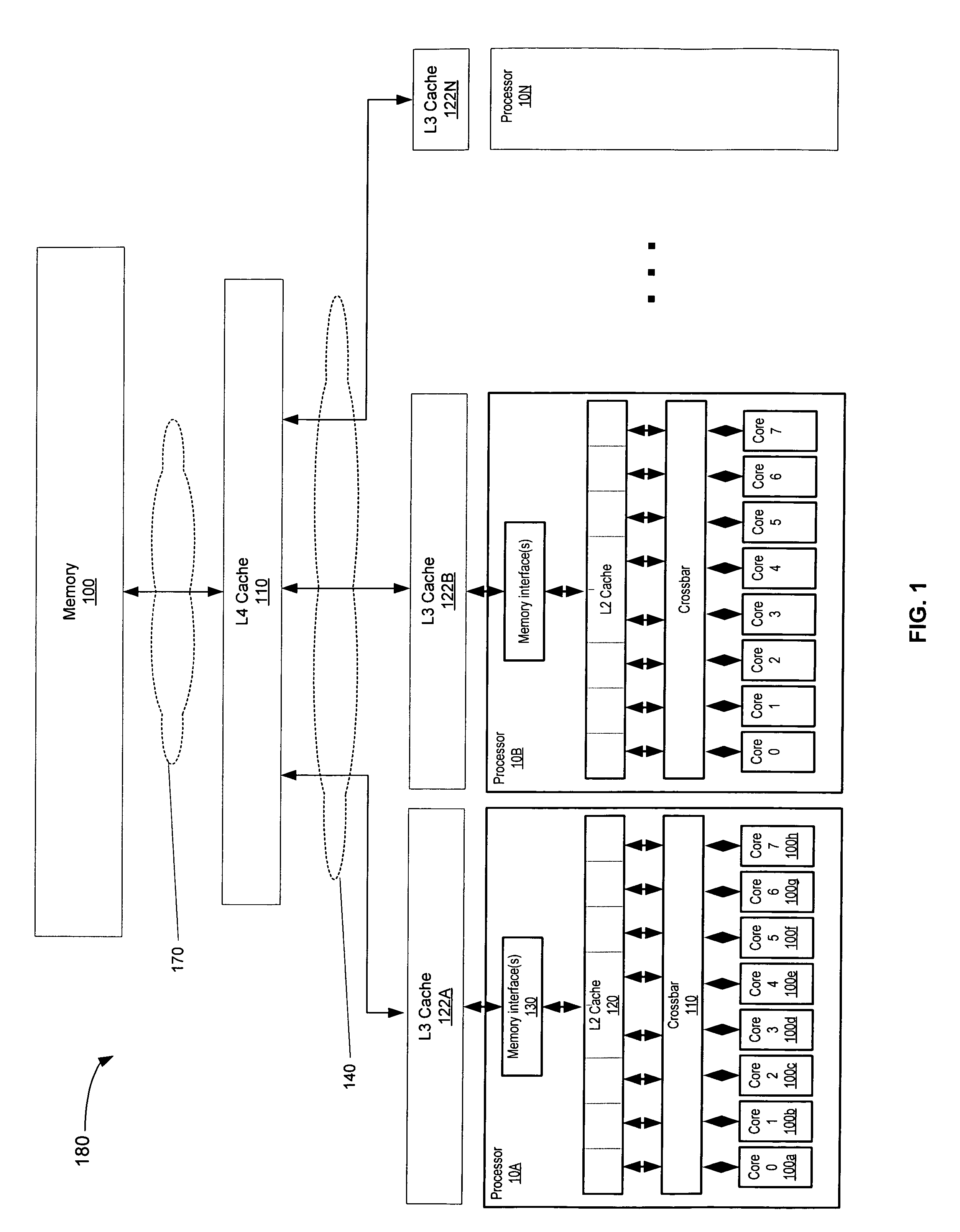
[0024]FIG. 1 depicts one embodiment of a shared memory computing system 180. In the embodiment shown, system 180 includes multiple processors 10A-10N. As shown, processor 10A comprises a plurality of processing cores 100a-h, which are also designated “core 0” through “core 7”. Each of cores 100 is coupled to a level 2 (L2) cache 120 via a crossbar 110. L2 cache 120 is coupled to one or more memory interface(s) 130. In addition, each processor 10 is coupled to a level 3(L3) cache 122A-N. Each L3 cache 122 is coupled in turn to a level 4(L4) cache 110 via interconnect(s) 140. Finally, the L4 cache 110 is coupled to a shared system memory 100 via interconnect(s) 170. Interconnects 140 and 170 may comprise point-to-point based, bus based, or other types of interconnects known in the art. In one embodiment, each of processors 10 is similarly configured, though embodiments which include differently configured processors are contemplated as well. Elements referred to herein with a particul...


PUM


Abstract

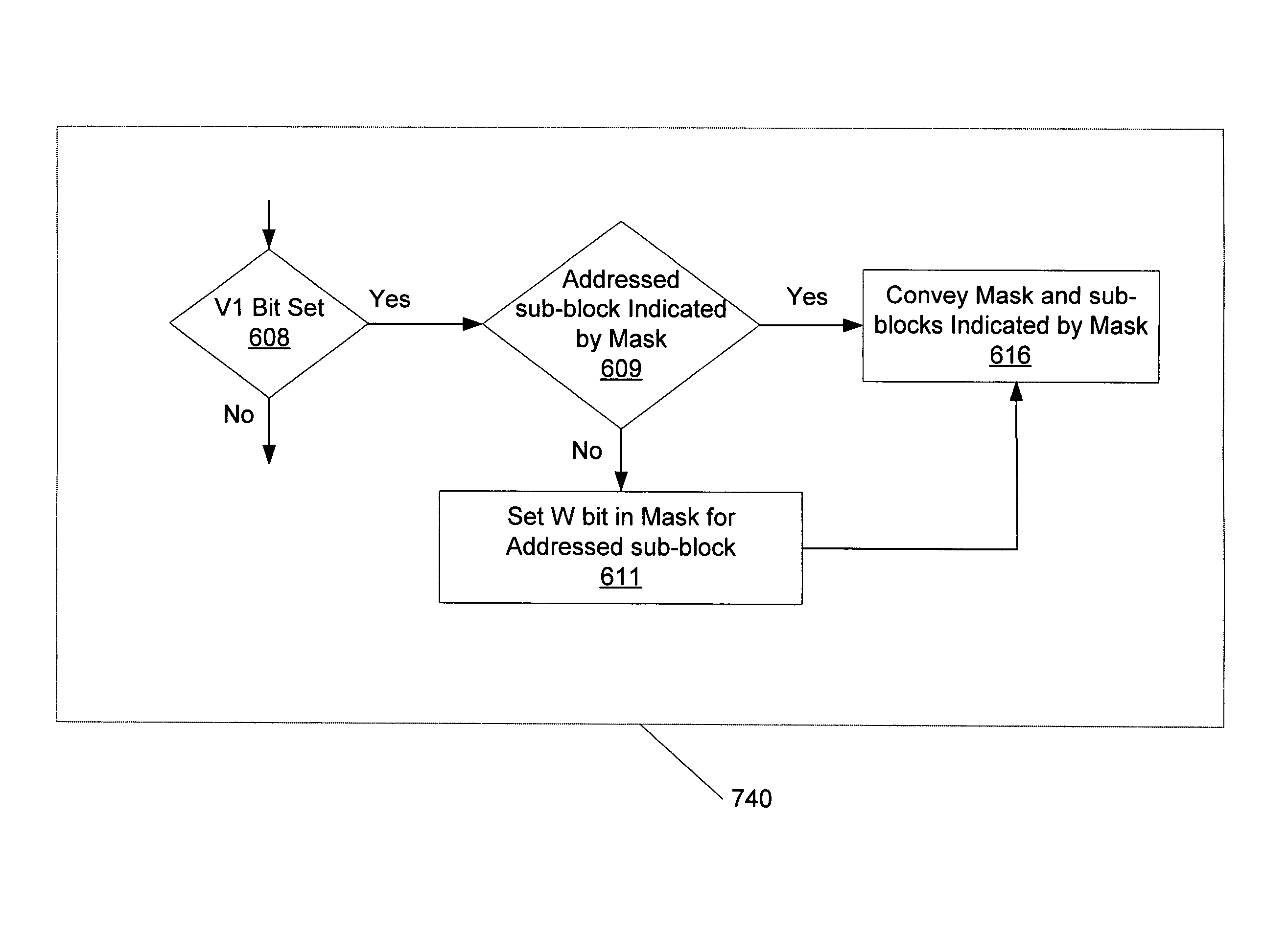
A method and mechanism are managing caches. A cache is configured to store blocks of data based upon predictions of future accesses. Each block is partitioned into sub-blocks, and if it is predicted a given sub-block is unlikely to be accessed, the sub-block may not be stored in the cache. Associated with each block is a mask which indicates whether sub-blocks of the block are likely to be accessed. When a block is first loaded into the cache, the corresponding mask is cleared and an indication is set for the block to indicate a training mode for the block. Access patterns of the block are then monitored and stored in the mask. If a given sub-block is accessed a predetermined number of times, a bit in the mask is set to indicate that the sub-block is likely to be accessed. When a block is evicted from the cache, the mask is also transferred for storage and only the sub-blocks identified by the mask as being likely to be accessed may be transferred for storage. If previously evicted data is restored to the cache, a previously stored mask is accessed to determine which of the sub-blocks are predicted likely to be accessed. The lower level storage may then transfer only those sub-blocks predicted likely to be accessed to the cache.

Description

BACKGROUND OF THE INVENTION[0001]1. Field of the Invention[0002]This invention is related to the field of computer systems and, more particularly, to memory systems in computer systems.[0003]2. Description of the Related Art[0004]Traditionally, the cost, performance, and power consumption characteristics of computer systems have been driven by the processors included in the system. More recently, however, trends in processor design have begun to shift attention to the main memory system. For example, chip multithreading (CMT) is becoming a more popular processor design. A CMT processor includes hardware on a single chip to concurrently process multiple independent software threads. The processor hardware may be shared among the threads, improving efficiency in the use of the processor hardware. However, having multiple threads in execution increases the demands on the memory system. While threads may be related to the same overall application and may share memory, in general each th...

Claims


Application Information

Patent Timeline
IPC IPC(8): G06F12/00G06F12/08
CPCG06F12/0804G06F12/0864G06F12/122G06F2212/1016
Inventor STENSTROM, PER O.
Owner ORACLE INT CORP
Learn More