Method of enabling low tier location applications

a low-tier, location application technology, applied in the direction of transmission monitoring, instruments, measurement devices, etc., can solve the problems of increasing the cost and size of the receiver, reducing the battery life, and reducing the efficiency so as to improve the efficiency and functionality of many mobile receiver applications, reduce the dependence on base station coordinates, and enhance the performance of such systems

Active Publication Date: 2011-11-01
GOOGLE TECH HLDG LLC
View PDF16 Cites 37 Cited by
  • Summary
  • Abstract
  • Description
  • Claims
  • Application Information

AI Technical Summary

Benefits of technology

[0013]Alternatively, the mobile unit may employ zone location information to reduce its reliance on more demanding location resolution systems (or arguably enhance performance of such systems), such as GPS. For example, if the mobile unit can resolve its location to a particular zone (such as a cellular service area of a known radius and a known base station coordinate location), then it may be possible selectively to eliminate some possible coordinate locations that otherwise are solutions to a GPS location calculation. In that way, the location of the mobile unit may be resolved to a resolutio

Problems solved by technology

The GPS location technique may be accurate but require an investment in hardware and require processing capabilities at the receiver, thus increasing the receiver cost and size or reducing battery life.
The coordinate location of the base station may be known in this manner, but the base station coordinates are not useful to the subscriber units

Method used


Image

  • Method of enabling low tier location applications
  • Method of enabling low tier location applications
  • Method of enabling low tier location applications

Examples


Embodiment Construction

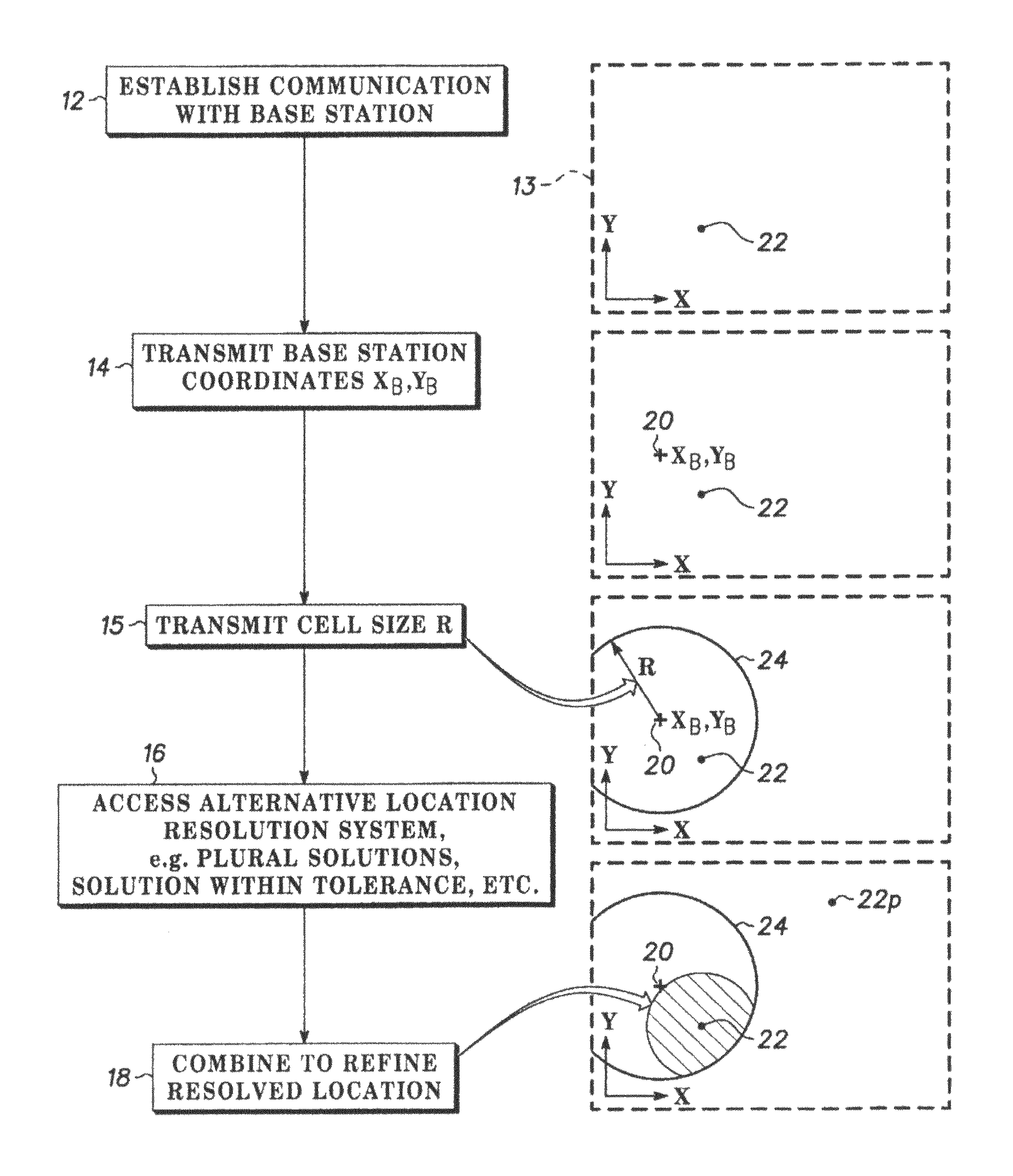
[0020]Referring to FIGS. 1-4, preferred embodiment of the invention can be advantageously employed in a wireless communication network having distributed base stations that service wireless devices in service areas or cells. Typically the wireless devices are cellular telephones, but they can be of any type, including for example, personal digital assistants, vehicle communication systems, local or personal area networks such as Bluetooth, or the like.

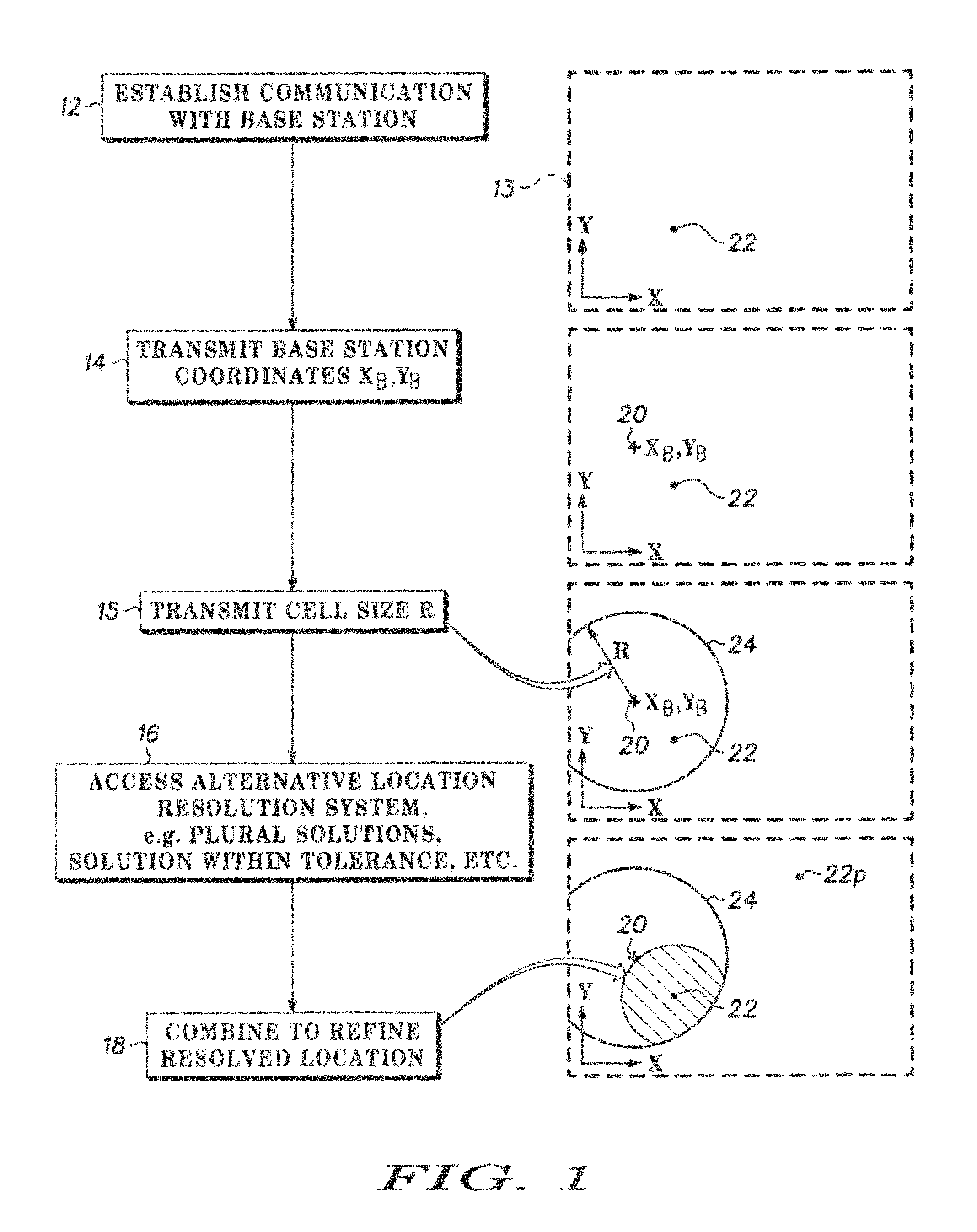
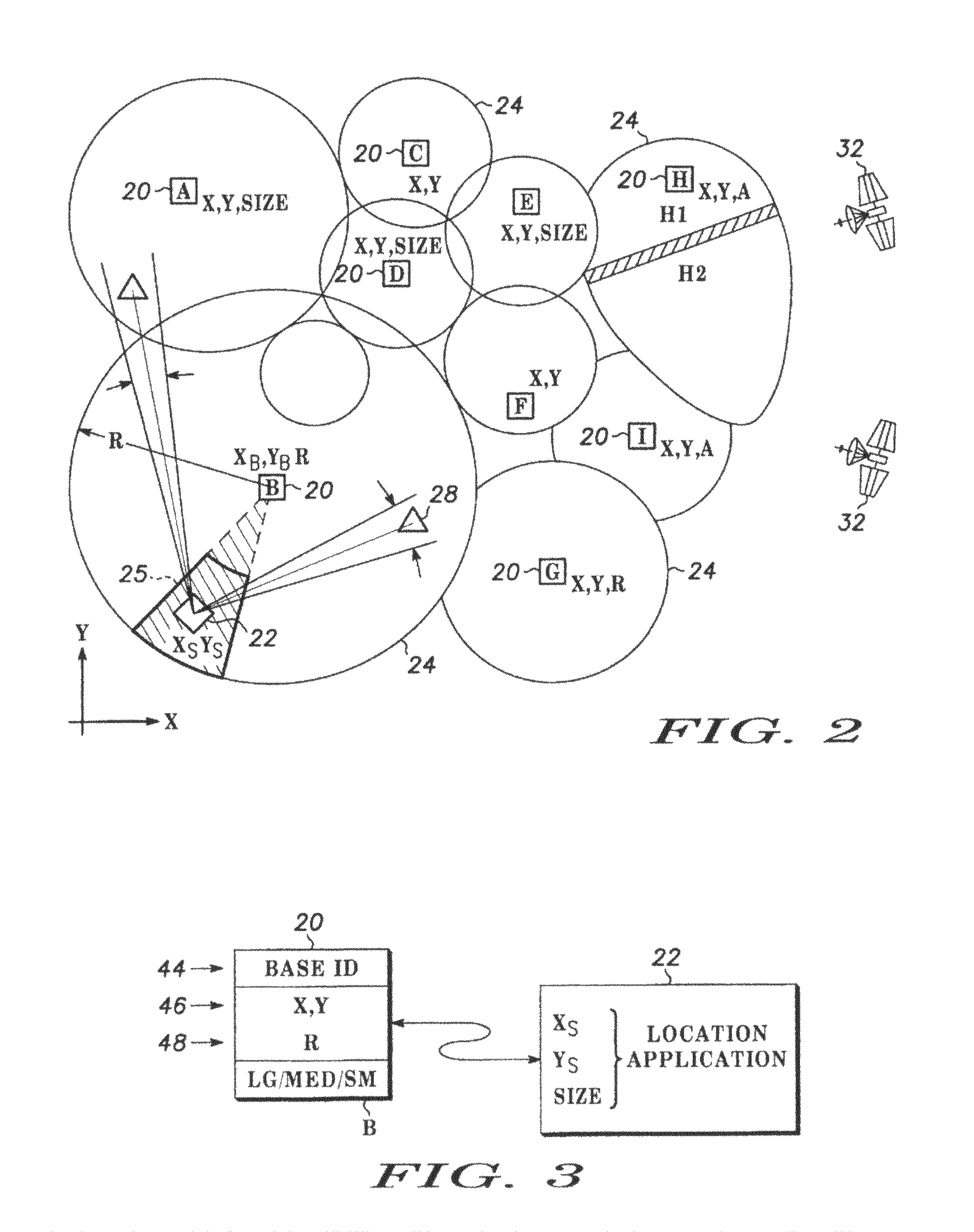
[0021]FIG. 1 illustrates a series of steps according to the invention, and FIG. 2 shows the implications and benefits in certain particular situations. The base stations 20 are indicated by square symbols in FIG. 2 and are designated A through I. The wireless devices 22 (indicated by diamond symbols) operate any of various applications programs, alone or in conjunction with their users. The applications of interest concern the spatial location of the wireless devices or subscriber units 22, in their respective service areas or cells 24...


PUM


Abstract

In a wireless communication network having remote receivers (subscriber units) communicating through base units in a service area, each of the base units servicing a cell area encompasses one or more identifiable zones which can be occupied by receivers. According to the invention, at least one measure of the spatial size of the cell is reported to a receiver communicating with a base station, for use in location specific applications. The measure can be a size category, an average diameter or another measure, such as a shape and orientation of the cell, a boundary apex, and a boundary line of the cell. The base station coordinates are conventionally available to the receiver. By providing a measure of size, the receiver can resolve its zone or location to a coarse or low level of resolution. The zone occupied by the receiver is at least within the cell and the size of the cell and location of the base station are now known. According to additional embodiments, the resolved zone known to be occupied by the receiver is refined to an area within the defined cell area. The size of the cell or service area of the location transmitter can be appended to the identification code of the base station. Reporting the cell size and location is sufficient to facilitate some location applications in the receiver, and can reduce or eliminate reliance on satellite and other positioning systems, particularly if the zone initially defined as the cell size is resolved further, for example using time-of-arrival, power level, angular bearing and similar techniques.

Description

FIELD OF THE INVENTION[0001]The invention relates to providing location information for wireless subscriber units in a communications network, for example a cellular telephone system or other network. In particular, one or more dimensions of a zone that a subscriber unit is known to occupy, is determined and made available by communicating with the subscriber unitBACKGROUND OF THE INVENTION[0002]There are various applications in which it is useful for a movable communications unit or its user to know the location of the unit, such as its coordinates in latitude and longitude or other reference system. Locating a person in need, helping a user to find a desired location such as a business, tracking assets during shipment, and locating stolen vehicles, are examples. Depending on the situation, the location information might be used at the subscriber unit or at the base station or at another unit in the network.[0003]The Telecommunication Industry Association (TIA) has adopted wireless...

Claims


Application Information

Patent Timeline
IPC IPC(8): H04W24/00
CPCG01S5/0236G01S5/12H04W64/00
Inventor SOUISSI, SLIMGUTOWSKI, GERALD J.
Owner GOOGLE TECH HLDG LLC
Why Eureka
Try Eureka