Structure mounting an electricity storage pack on a vehicle

a technology for mounting structures and electricity storage packs, which is applied to electric devices, cell components, tractors, etc., can solve the problems of electricity storage equipment that may receive physical impact or the like further directly, and cannot be protected appropriately, so as to reduce or prevent damage to the electricity storage pack

Active Publication Date: 2011-11-08
TOYOTA JIDOSHA KK
View PDF88 Cites 115 Cited by
  • Summary
  • Abstract
  • Description
  • Claims
  • Application Information

AI Technical Summary

Benefits of technology

The present invention contemplates a structure mounting an electricity storage pack on a vehicle, that can reduce or prevent damage to the electricity storage pack when the vehicular body or the electricity storage pack receives physical impact.

Problems solved by technology

For example when vehicles collide with each other and the electricity storage pack directly receives physical impact, the electricity storage pack may receive physical impactive force and be damaged, or sudden braking or the like may cause a load on the vehicle to impinge on the electricity storage pack and thus exert physical impactive force to the electricity storage pack.
Furthermore even if the electricity storage pack does not receive physical impact directly, being bumped by a vehicle from behind or the like may deform the support member, and as the supporting member is deformed, the electricity storage pack per se may receive a load.
Furthermore, as the supporting member is deformed, the electricity storage pack may come off the support member, smash another portion and thus experience physical impactive force.
In particular, if the electricity storage pack has damaged a case accommodating a storage battery or similar electricity storage equipment and the internal electricity storage equipment is exposed, the electricity storage equipment may receive physical impact or the like further directly and may not be protected appropriately.

Method used


Image

  • Structure mounting an electricity storage pack on a vehicle
  • Structure mounting an electricity storage pack on a vehicle
  • Structure mounting an electricity storage pack on a vehicle

Examples


first embodiment

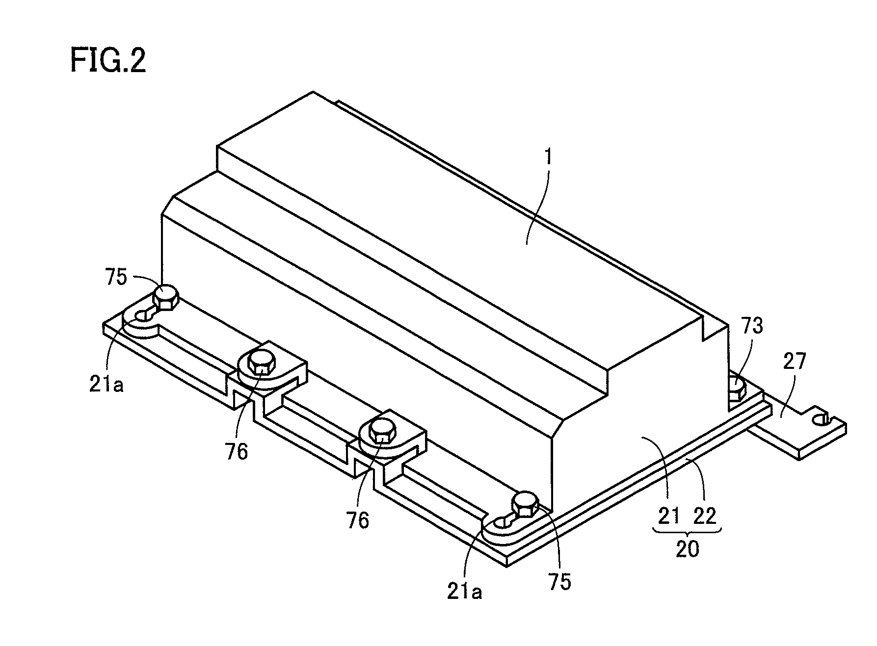
Reference will now be made to FIG. 1 to FIG. 9 to describe a structure mounting an electricity storage pack on a vehicle in a first embodiment of the present invention.

A secondary battery, a capacitor or similar electricity storage equipment is accommodated in a case and thus mounted in a vehicle. In the present invention, equipment including the case and the electricity storage equipment accommodated in the case will be referred to as an electricity storage pack. The electricity storage pack may include other internal components including such as a cooling device such as a cooling duct, a cooling fan and the like for cooling the electricity storage equipment, electronics converting power, and the like.

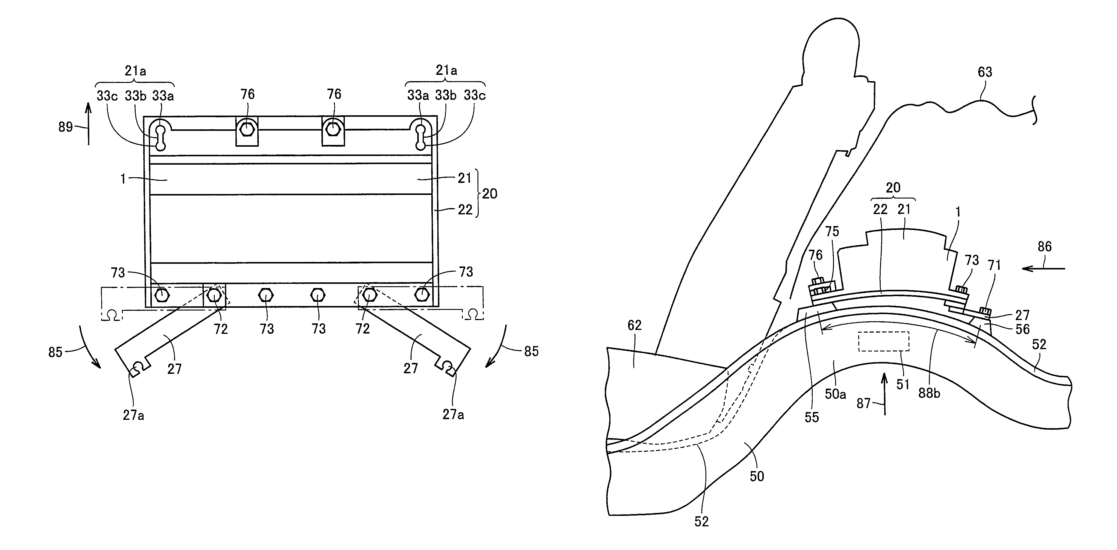
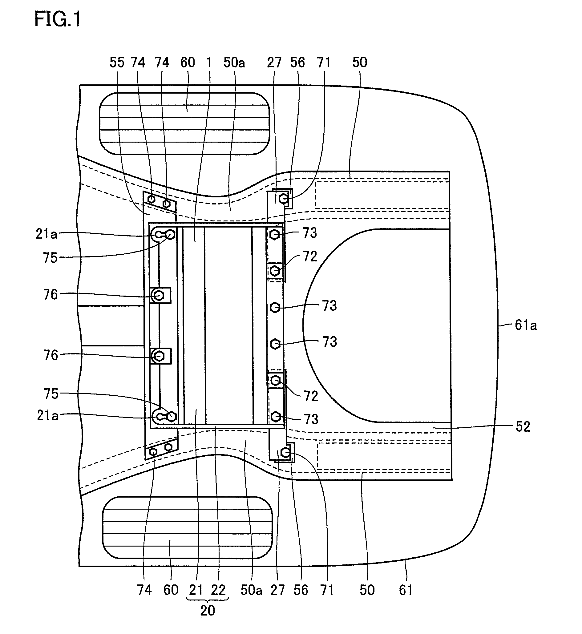
FIG. 1 is a schematic cross section of the portion of the battery pack in the present embodiment. FIG. 1 shows a rear portion of a vehicular body. In the present invention a so-called sedan vehicle will be described. The vehicle includes a body 61. Body 61 is formed to be generally a ...

second embodiment

With reference to FIG. 10, the present invention in a second embodiment provides a structure mounting an electricity storage pack on a vehicle, as will be described hereinafter. The present embodiment provides a structure mounting an electricity storage pack on a vehicle, that supports the electricity storage pack's front portion by a structure different from that described in the first embodiment.

FIG. 10 is a schematic cross section of a structure mounting a battery pack on a vehicle in the present embodiment. In the present embodiment the structure mounting a battery pack on a vehicle employs four securing members to secure a battery pack to a support member.

The structure mounting a battery pack on a vehicle includes a securing member implemented as a front bracket 45 disposed at a front end of a battery pack 2. Battery pack 2 includes an upper case 41 and a lower case 42. Upper case 41 and lower case 42 are fastened together by bolts 73, 77.

Front bracket 45 is pivotably coupled t...

third embodiment

With reference to FIG. 11 to FIG. 14B, the present invention in a third embodiment provides a structure mounting (or attaching) an electricity storage pack to a vehicle, as will be described hereinafter.

With reference to FIG. 11, the present embodiment provides a structure mounting an electricity storage pack on a vehicle, that has an electricity storage pack implemented as a battery pack 3 having an end closer to the front side of the vehicular body that is supported by side member 50 via mount 55 and floor member 52, and an end closer to the rear side of the vehicular body that is supported by side member 50 via a mount 56a and floor member 52, rather than rear bracket 27 described in the first embodiment. The remainder in configuration similar to that of the first embodiment will be identically labeled and will not be described repeatedly.

The present embodiment provides battery pack 3 including an upper case 301 and a lower case 302. Similarly as has been described in the first e...


PUM

PropertyMeasurementUnit
lengthaaaaaaaaaa
rigidityaaaaaaaaaa
forceaaaaaaaaaa

Abstract

There are included a side member formed to support a battery pack, and a rear bracket securing the battery pack to the side member. The rear bracket has one side pivotably coupled to the battery pack, and the other side pivotably coupled to the side member.

Description

TECHNICAL FIELDThe present invention relates to structures mounting an electricity storage pack on a vehicle.BACKGROUND ARTIn recent years an electric vehicle employing a motor as a driving source and a so called hybrid electric vehicle having a motor serving as a driving source and another driving source combined together are commercially available. Such vehicles have electricity storage equipment mounted therein for supplying the motor with electricity serving as energy. The electricity storage equipment is implemented for example as a secondary battery represented by a repeatedly rechargeable and dischargeable nickel cadmium battery, nickel hydrogen battery, lithium ion battery and the like, a capacitor and the like. The electricity storage equipment is accommodated in a case and thus mounted as an electricity storage pack on a vehicular body.Japanese Patent Laying-Open No. 2001-113959 proposes a vehicular battery mounting structure including a battery trestle bearing a battery b...

Claims


Application Information

Patent Timeline
Patent Type & Authority Patents(United States)
IPC IPC(8): B60R16/04H01M50/209H01M50/242H01M50/244H01M50/249
CPCB60K1/04B60L3/0007B62D25/2027H01M2/1083H01M2/347B60L11/1877B60K2001/0416B60K2001/0433B60K2001/0494Y02T10/705Y02T10/7005Y02T10/7011B60L50/66B60L50/64Y02T10/70Y02E60/10H01M50/579H01M50/249H01M50/209H01M50/242H01M50/244
Inventor KIYA, NOBUAKINOMURA, BUNJI
Owner TOYOTA JIDOSHA KK
Why Eureka
Try Eureka