Laser-based methods of stripping fiber optic cables

a fiber optic cable and laser stripping technology, applied in the field of laser stripping fiber optic cables, can solve the problems of affecting the performance of the fiber optic cable, the harness not meeting the required tolerances, and having to be scrapped, and the drawbacks of stripping tools

Active Publication Date: 2011-11-08
CORNING OPTICAL COMM LLC
View PDF5 Cites 38 Cited by
  • Summary
  • Abstract
  • Description
  • Claims
  • Application Information

AI Technical Summary

Benefits of technology

[0006]The disclosure provides for laser-based methods of stripping different types of fiber optic cables. The methods generally include directing a focused laser beam onto the cable's protective cover and moving the fiber optic cable relative to the focused laser beam in a direction substantially along the central axis to form a substantially axially oriented groove in the protective cover. In one ex

Problems solved by technology

Such damage can lead to optical transmission degradation (i.e., attenuation of the transmitted optical signal) or fiber breakage, either of which results in the harness failing to meet the required tolerances and having to be scrapped.
However, these stripping tools have significant drawbacks.
One drawback is that they rely upon the skill and experience of the craftsperson to cut through the protective cover without damaging or stressing

Method used


Image

  • Laser-based methods of stripping fiber optic cables
  • Laser-based methods of stripping fiber optic cables
  • Laser-based methods of stripping fiber optic cables

Examples


Embodiment Construction

[0025]Reference is now made in detail to example embodiments of the disclosure, examples of which are illustrated in the accompanying drawings. Whenever possible, the same or like reference numbers and symbols are used throughout the drawings to refer to the same or like elements or components.

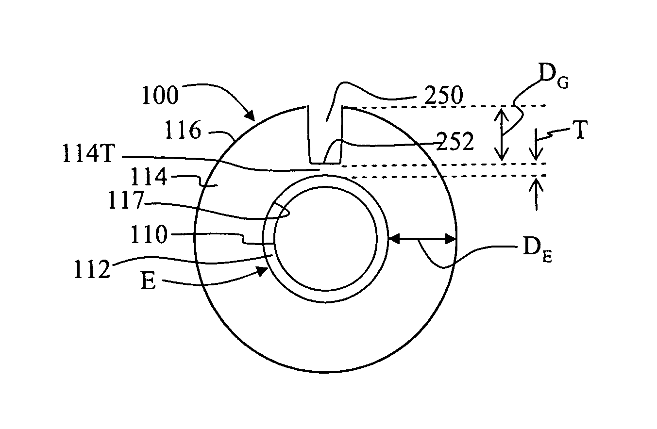
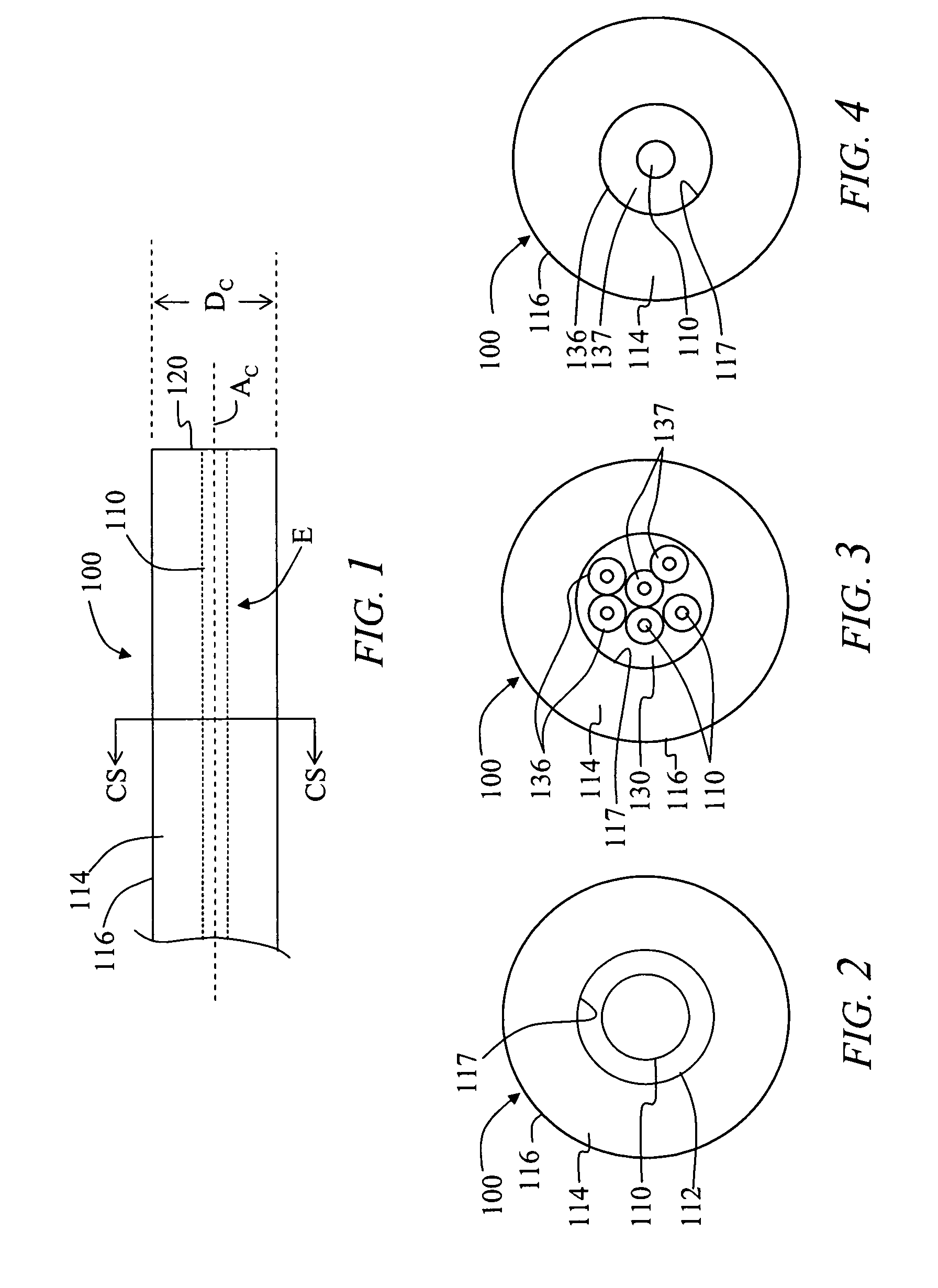
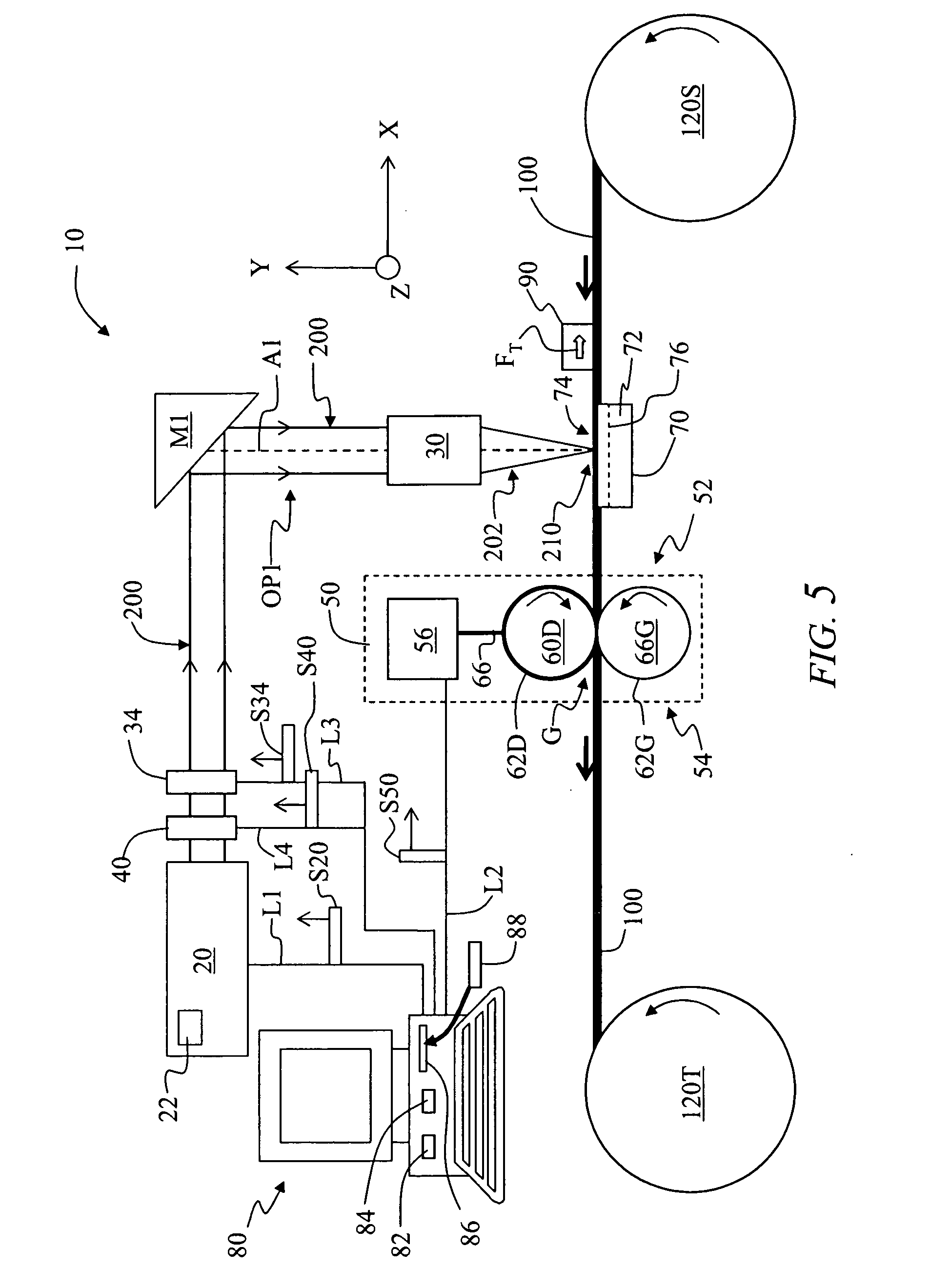
[0026]One aspect of the disclosure is a method of stripping a fiber optic cable having a protective cover with an outer surface that surrounds at least one optical fiber and that has a cable diameter (DC) and a central axis. The method includes directing at least one focused laser beam onto the protective cover. The method further includes moving the fiber optic cable relative to the at least one focused laser beam in a direction substantially along the central axis to form at least one substantially axially oriented groove in the protective cover, wherein the at least one groove does not reach the at least one optical fiber. The method also includes opening the protective cover at the at leas...


PUM

PropertyMeasurementUnit
Electrical conductanceaaaaaaaaaa
Thicknessaaaaaaaaaa
Diameteraaaaaaaaaa

Abstract

Laser-based methods of stripping different types of fiber optic cables (100) are disclosed. The method includes directing a focused laser beam (202) onto the cable's protective cover (114). The method also includes moving the fiber optic cable relative to the focused laser beam in a direction substantially along a central axis (AC) to form a substantially axially oriented groove (250) in the protective cover, wherein the groove does not reach one or more optical fibers (110) carried by the cable. The method can further include opening the protective cover at the groove to form a split protective cover portion (114S), and removing the split protective cover portion from the fiber optic cable. Methods of stripping a cable by forming two grooves in the protective cover using two focused laser beams are also disclosed.

Description

FIELD[0001]The disclosure relates to fiber optic cables, and to laser-based methods of stripping the protective outer jacket from fiber optic cables.BACKGROUND[0002]Fiber optic cables are the backbone of optical fiber telecommunication networks. Multiple fiber optic cables are often included in a “harness,” with the individual cables broken out at the end of the harness to connect to different locations.[0003]Fiber optic cables used in harnesses can be classified into three main groups: tight-buffered cables, loose-tube cables, and single-tube cables. Tight-buffered cables are designed for indoor applications, have very good flexibility, and can be bent with a relatively small bend radius. One example tight-buffered cable uses a 125 μm diameter fiber with a low-friction acrylate layer that extends to an outside diameter of 250 μm. Next, a polymer buffer layer is added to the outside diameter of the low friction layer to form a protective cover that has an outside diameter of 900 μm....

Claims


Application Information

Patent Timeline
IPC IPC(8): B32B38/10
CPCB23K26/0621B23K26/0846B23K26/367B23K26/4075G02B6/4497B23K26/0676Y10T156/1917B23K2201/34B23K2201/40H02G1/128Y10S156/923Y10T156/1158Y10T156/1168Y10T156/11Y10T156/1961B23K26/364B23K26/0619B23K26/40B23K2101/34B23K2101/40B23K2103/50G02B6/566
Inventor CALE, ANDREW STEPHENDANLEY, JEFFREY DEANDEAN, JR., DAVID LEECOOKE, TERRY LEEMABRY, III, CLYDE BENTONMILLER, DARRIN MAX
Owner CORNING OPTICAL COMM LLC
Why Eureka
Try Eureka