Method for object tracking

a tracking method and object technology, applied in the field of object tracking, can solve the problems of difficult modeling of the movement between two images taken sequentially by the camera device, objects to be tracked, pedestrians,

Active Publication Date: 2011-11-08
APTIV TECH LTD
View PDF2 Cites 22 Cited by
  • Summary
  • Abstract
  • Description
  • Claims
  • Application Information

AI Technical Summary

Benefits of technology

[0004]It is therefore the underlying object of the present invention to provide a method of the initially named kind which is in a position to deliver reliable results with a computing effort which is as low as possible.
[0006]In the method in accordance with the invention, it is therefore not, for instance, a three-dimensional movement which is tracked, but rather only a movement of one or more spatial points in the road plane. The computing effort required for the object tracking can thereby be considerably reduced. In addition, objects which do not move exclusively in the road plane are automatically filtered out. Since those objects whose tracking is sensible for an application in the motor vehicle, i.e. pedestrians, cyclists and any desired vehicles, always move substantially in the road plane, computing power is saved in a sensible manner by this filtering. It is namely avoided, without any additional effort in the object recognition, that computing power is used for the tracking of moving objects not of interest in the present context such as birds, branches moved by the wind, etc.
[0012]The state estimator preferably uses a linear system equation to compute the estimated value for the state vector. The calculation is thereby simplified.

Problems solved by technology

A difficulty of such applications in this connection is that not only the object to be tracked, for example a pedestrian, is moving, but also the camera fixed to the vehicle.
These two movements overlap and the resulting movement between two images taken sequentially by the camera device is difficult to model.
It has previously not been possible to provide a satisfactory method for object tracking with the assistance of a moving camera.
On the one hand, the quality of the predictions which can be achieved with conventional processes is often not satisfactory; on the other hand, a comparatively large computing power is needed to evaluate the images taken by the camera in real time.

Method used


Image

  • Method for object tracking
  • Method for object tracking
  • Method for object tracking

Examples


Embodiment Construction

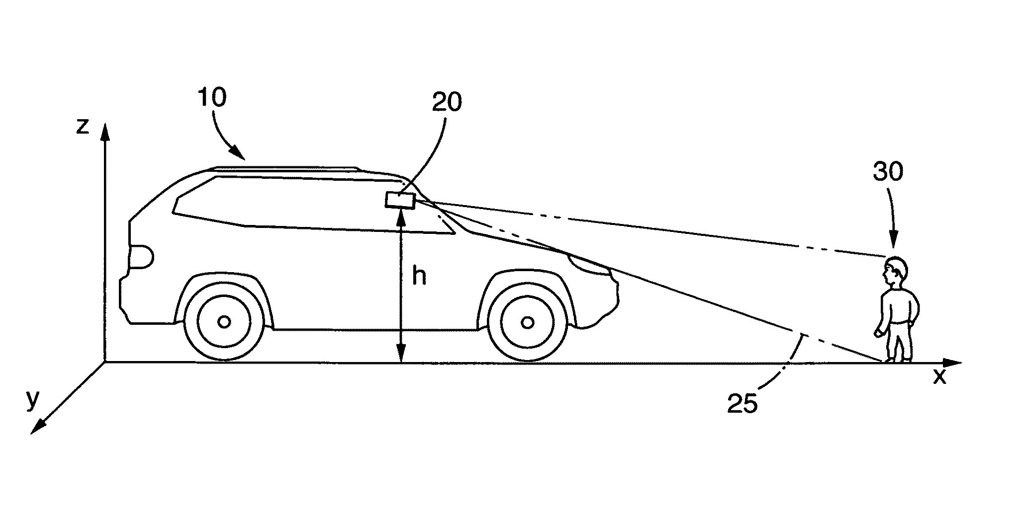
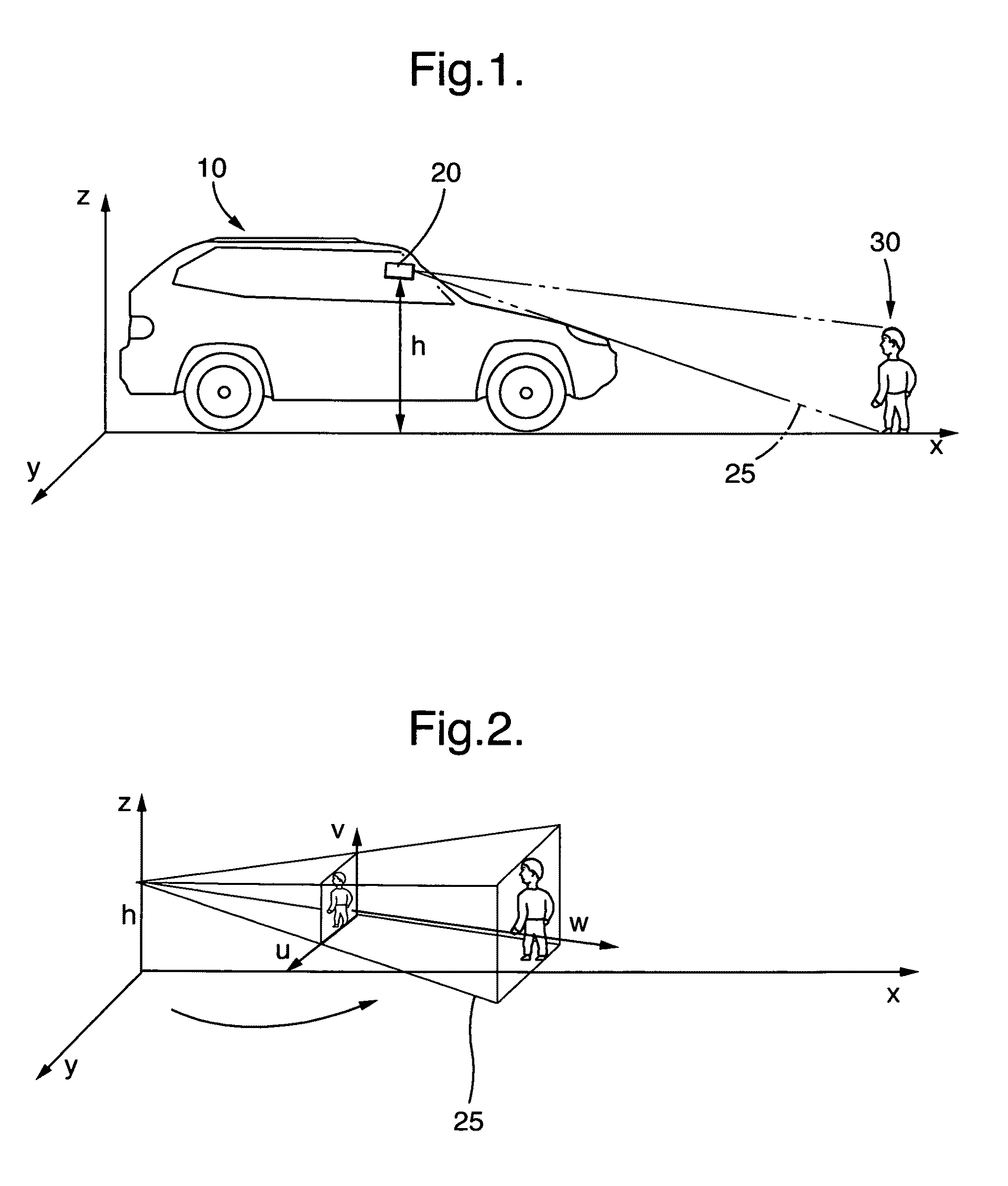
[0030]FIG. 1 shows a motor vehicle 10 having a camera device 20 attached in a front region of the vehicle headlining. The camera device 20 takes an image of the environment comprising picture elements in the visual range of the camera device. It covers a pedestrian 30, as is indicated by the directional beams 25.

[0031]The space in which both the vehicle 10 and the pedestrian 30 move is spanned by the three coordinate axes x, y, z, with the x-y plane (z=0) corresponding to a road plane. The camera device 20 is above the road plane by a height h.

[0032]With the help of an image processing system, those picture elements u, v, are identified in the taken image which correspond to a pedestrian to be tracked 30. An picture element u, v is then extracted for this pedestrian 30 which represents a projection in image coordinates of that spatial point at which the object to be tracked contacts a road plane.

[0033]FIG. 2 illustrates the projection from the space x, y, z in image coordinates u, v...


PUM


Abstract

The present invention relates to a method for the recognition and tracking of a moving object, in particular of a pedestrian, from a motor vehicle, at which a camera device is arranged. An image of the environment including picture elements is taken in the range of view of the camera device (20) by means of the camera device at regular time intervals and those picture elements are identified with the help of an image processing system which correspond to moving objects to be tracked. A picture element is extracted for each of these objects which represents a projection in image coordinates of that spatial point at which the object contacts a road plane The movement of the corresponding spatial point in the road plane is tracked by means of a state estimator which uses an at least four-dimensional state vector whose components are a position of the spatial point in the road plane and an associated speed in the road plane, wherein the tracking of the movement by the state estimator includes the steps that a prediction is generated for the state vector, this prediction is converted into image coordinates via suitable projection equations, an error to be expected for this prediction is calculated in image coordinates by means of a covariance matrix, and this prediction is compared with the picture element extracted in a later image and is updated.

Description

TECHNICAL FIELD[0001]The present invention relates to a tracking method for the recognition and tracking of a moving object. It more precisely relates to a method for the recognition and tracking of a moving object, in particular a pedestrian, from a motor vehicle. In this connection, a camera device is arranged at the motor vehicle by means of which an image of the environment comprising picture elements in the range of view of the camera device is taken.BACKGROUND OF THE INVENTION[0002]Methods of this type for object tracking, so-called tracking methods, are generally known. Applications are also already known in the automotive sector in which tracking methods are used to track and predict the movement of a pedestrian or also of a cyclist or of another vehicle, so that an impending collision can be predicted at an early stage. The vehicle can be braked via a driver assistance system in the event of an impending collision, in particular with a pedestrian, or suitable safety devices...

Claims


Application Information

Patent Timeline
Patent Type & Authority Patents(United States)
IPC IPC(8): G06K9/00H04N5/225
CPCG06K9/3241G06K9/00805G06T7/20G06V20/58G06V10/255
Inventor MEUTER, MIRKOIURGEL, URI
Owner APTIV TECH LTD
Why Eureka
Try Eureka