Combination wedge bonding and ball bonding transducer

a transducer and wedge bonding technology, applied in the field of manual wire bonding machines, can solve the problems of damage (and even breakage) of the curved surface, not desired for wedge bonding,

Active Publication Date: 2011-11-15
KULICKE & SOFFA IND INC
View PDF3 Cites 9 Cited by
  • Summary
  • Abstract
  • Description
  • Claims
  • Application Information

AI Technical Summary

Problems solved by technology

Unfortunately, the tightening mechanism (e.g., the screw mechanism) is more properly configured to secure only one type of tool.
For example, in a transducer configured for ball bonding, one conventional design is to use a split clamp aperture to receive the bonding tool, wherein a screw is provided on a side of the transducer adjacent the bonding tool aperture, whereby the screw tightens the split clamp aperture around the bonding tool; however, such an arrangement is not desired for wedge bonding because, for example, the wedge bonding tool is not automatically aligned by such an arrangement (amongst other reasons).
Likewise, in a transducer configured for wedge bonding, one conventional design is to use a screw provided on a front tip portion of the transducer, whereby the screw tightens against a flat surface of the wedge bonding tool; however, such an arrangement is not desired for ball bonding because, for example, the screw may damage (and even break) the curved surface of the ball bonding tool.

Method used


Image

  • Combination wedge bonding and ball bonding transducer
  • Combination wedge bonding and ball bonding transducer
  • Combination wedge bonding and ball bonding transducer

Examples


Embodiment Construction

[0023]According to certain exemplary embodiments of the present invention, a transducer is provided (e.g., a transducer for 60 kHz or other frequency wire bonding). The transducer is designed to provide correct mounting for ball bonding (capillary tools) and wedge bonding (wedge bond tools). The transducer assembly includes mounting features for both ball bonding tools and wedge bonding tools.

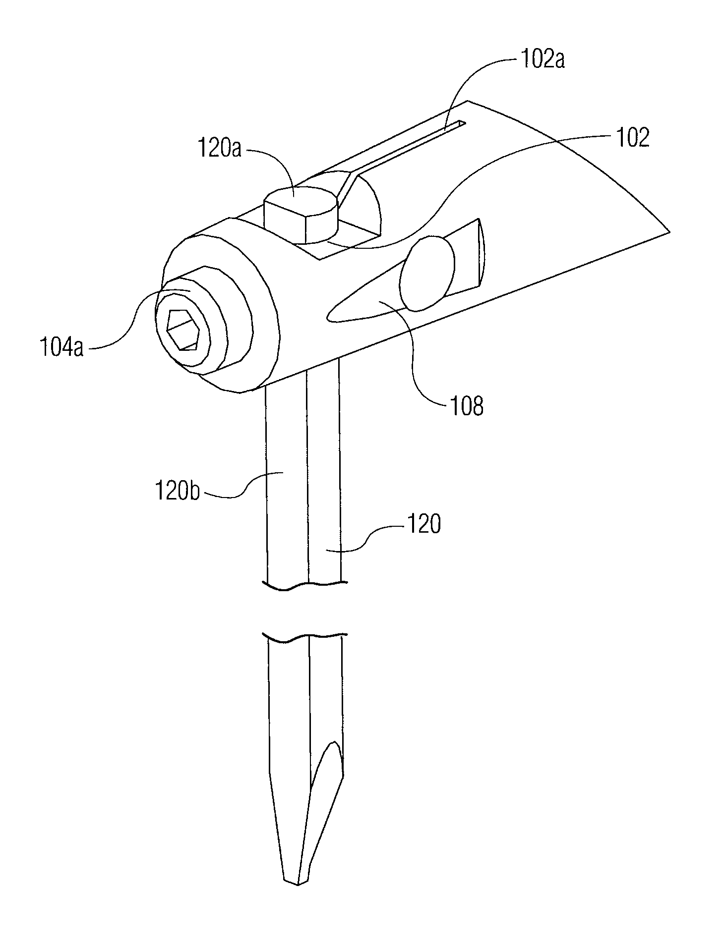
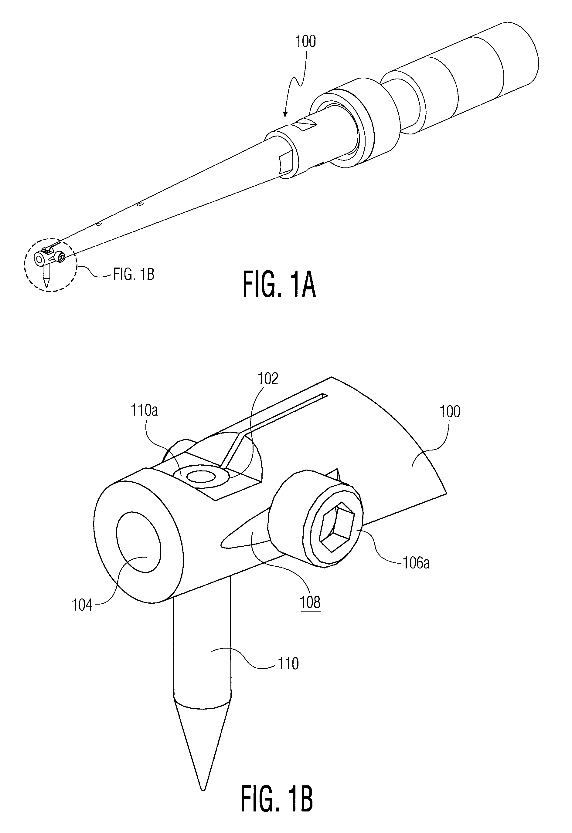
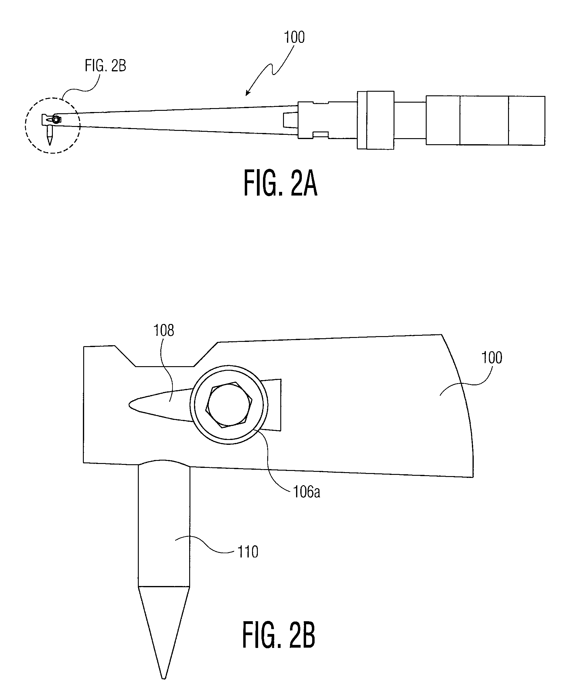
[0024]Referring now to FIGS. 1A-1B, 2A-2B, and 3A-3B, various views are provided of transducer 100 holding ball bonding capillary tool 110. In contrast, referring to FIGS. 4A-4B, 5A-5B, and 6A-6B, various views are provided of transducer 100 holding wedge bonding tool 120.

[0025]Referring specifically to the perspective views provided in FIGS. 1A-1B, transducer 100 includes an end portion that is shown in the detailed view of FIG. 1B. As shown in FIG. 1B, first tightening mechanism 106a (e.g., a threaded screw member or the like) is used secure ball bonding capillary tool 110 within bonding tool...


PUM

PropertyMeasurementUnit
frequencyaaaaaaaaaa
electrically interconnectedaaaaaaaaaa
volumeaaaaaaaaaa

Abstract

A transducer configured for use with a manual wire bonding machine includes a body portion including an end portion, the end portion defining a bonding tool aperture configured to receive at least a portion of a bonding tool. The transducer also includes a first tightening mechanism for securing a ball bonding tool in the bonding tool aperture, and a second tightening mechanism for securing a wedge bonding tool in the bonding tool aperture. The first tightening mechanism is distinct from the second tightening mechanism.

Description

CROSS-REFERENCE TO RELATED APPLICATION[0001]This application claims the benefit of U.S. Provisional Application No. 60 / 828,676, filed Oct. 9, 2006, the contents of which are incorporated herein by reference.FIELD OF THE INVENTION[0002]The present invention relates to manual wire bonding machines, and more particularly, to a transducer for manual wire bonding machines configured for ball bonding and wedge bonding.BACKGROUND OF THE INVENTION[0003]In the processing and packaging of semiconductor devices, wire bonding continues to be the primary method of providing electrical interconnection between two locations within a package (e.g., between a die pad of a semiconductor die and a lead of a leadframe). More specifically, using a wire bonder (also known as a wire bonding machine) wire loops are formed between respective locations to be electrically interconnected.[0004]Manual wire bonding machines (in contrast to automatic wire bonding machines) are often purchased by low volume users,...

Claims


Application Information

Patent Timeline
Patent Type & Authority Patents(United States)
IPC IPC(8): B23K20/10
CPCB23K20/004B23K20/005B23K20/106H01L24/78H01L2224/78301H01L2224/78308H01L2224/78313H01L2924/00014H01L2924/01082H01L2924/01006H01L2924/01033H01L2224/48H01L2224/45099
Inventor AVRAHAM, LEANACHON, BENIMARTIN, JOSEPH M.
Owner KULICKE & SOFFA IND INC
Why Eureka
Try Eureka