Miniature and multi-band RF coil design

a technology of rf coils and coils, applied in the field of radio frequency coils, can solve the problems of affecting the frequency of operation, the impedance of the coil, and the impedance of the coil, and achieve the effect of reducing the overall volume of the rf coil and prolonging the wavelength

Inactive Publication Date: 2011-11-15
HONG KONG APPLIED SCI & TECH RES INST
View PDF19 Cites 107 Cited by
  • Summary
  • Abstract
  • Description
  • Claims
  • Application Information

AI Technical Summary

Benefits of technology

[0009]The use of current path discontinuities and / or shorting bridges can enable an RF coil designer to create an RF coil that has an impedance that is already matched to a transmission line. Thus, some embodiments can eliminate external LC matching circuits such as circuit 1302 of FIG. 13. Furthermore, a current path discontinuity and / or a shorting bridge can be used to shift the operating frequency of a given coil, even shifting the operating frequency downward, thereby getting a longer wavelength out of a smaller sized coil. By correct placement of the shorting bridge and / or current path discontinuity, the overall volume of the RF coil can be significantly reduced. Moreover, some embodiments provide for multi-band operations.

Problems solved by technology

The current path discontinuity adds some amount of capacitance to the RF coil, thereby affecting the frequency of operation, as well as the impedance of the coil.
The shorting bridge adds some amount of inductance to the coil and affects operating frequency and impedance.

Method used


Image

  • Miniature and multi-band RF coil design
  • Miniature and multi-band RF coil design
  • Miniature and multi-band RF coil design

Examples


Embodiment Construction

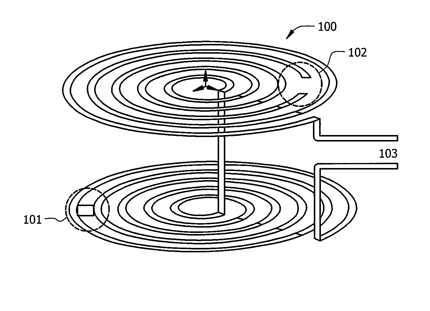
[0025]FIG. 1 is an illustration of exemplary RF coil 100 adapted according to one embodiment of the invention. RF coil 100 includes shorting bridge 101 and gap 102, which together affect the frequency performance of RF coil 100 as well as provide impedance matching at input / output port 103.

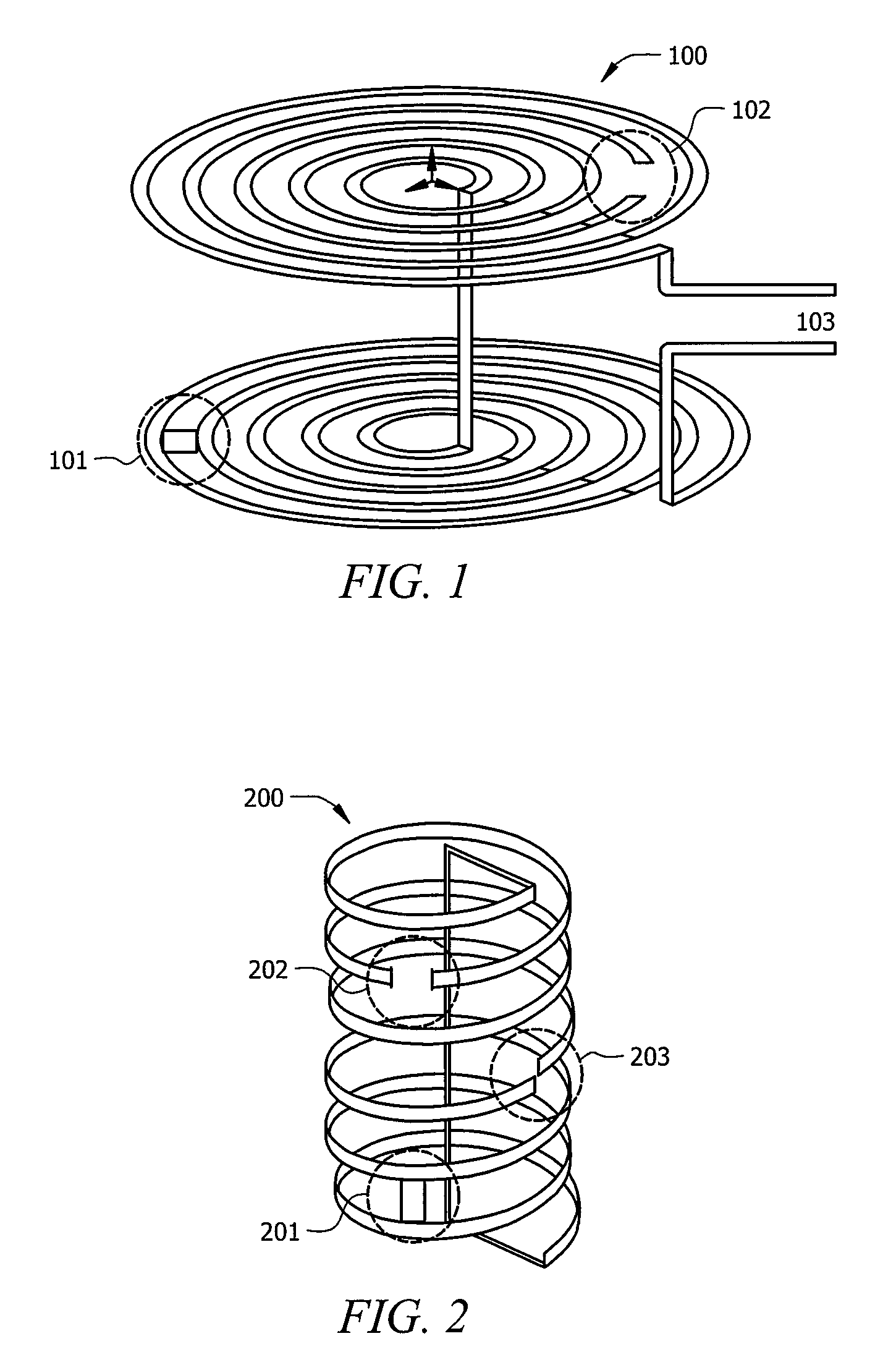
[0026]The scope of embodiments is not limited to the double-layer spiral type coil shown in FIG. 1. Embodiments of the invention can be adapted for use in any shape or type of RF coil, such as coils that include any number of layers, any number of turns, any sense of rotation in the turns, etc. For instance, FIG. 2 is an illustration of exemplary RF coil 200, adapted according to one embodiment of the invention. RF coil 200 is a helical type coil that includes shorting bridge 201 and gap 202 to provide impedance matching at input / output port 203 and frequency shifting.

[0027]Nor is the scope of embodiments limited to coils that have both a gap and a shorting bridge, as some embodiments include eith...


PUM

PropertyMeasurementUnit
magnetic fieldaaaaaaaaaa
frequencyaaaaaaaaaa

Abstract

A near field apparatus comprises a Radio Frequency (RF) coil including at least one of a shorting bridge from a first point to a second point along an electrical path of the RF coil and / or a discontinuity in the electrical path of the RF coil.

Description

TECHNICAL FIELD[0001]The present description relates, in general, to Radio Frequency (RF) coils and, more specifically, to RF coils with new techniques to provide frequency shifting and / or impedance matching.BACKGROUND OF THE INVENTION[0002]For wireless communication, far field transmission and reception of electromagnetic waves is familiar, even to consumers. Applications utilizing near field energy also exist and are becoming increasingly common.[0003]For instance, Radio Frequency Identification (RFID) applications usually employ near field transmitters and detectors. Structures used to transmit and receive near field energy are referred to as Radio Frequency (RF) coils (as opposed to antennas), and include structures such as loop coils, spiral coils, and dipole-like wires, etc. Thus, whereas the term “antenna” refers to a far field radiating structure, RF coils are understood to be for near field applications.[0004]An outgrowth of RFID is Near Field Communications (NFC), which is...

Claims


Application Information

Patent Timeline
Patent Type & Authority Patents(United States)
IPC IPC(8): G06K19/00H01Q13/00H01Q7/00H01Q21/00G08B1/08G06K19/06
CPCG01R33/34007G01R33/34046G01R33/34053G01R33/34061H01Q1/38H01Q7/00H01Q21/06G01R33/341Y10T29/49016G01R33/3628
Inventor ROWELL, CORBETT R.LAI, HAU-WAHMAK, CHI-LUN
Owner HONG KONG APPLIED SCI & TECH RES INST
Why Eureka
Try Eureka