Prevention quench in a magnetic resonance examination system

a magnetic resonance examination and quench technology, applied in the direction of superconducting magnets/coils, instruments, magnetic bodies, etc., can solve the problems of dynamic heat load, loss of dynamic ac in the windings of the main magnet coil, and increase the temperature of the main magnet, so as to achieve stable operation

Inactive Publication Date: 2011-11-15
KONINK PHILIPS ELECTRONICS NV
View PDF8 Cites 12 Cited by
  • Summary
  • Abstract
  • Description
  • Claims
  • Application Information

AI Technical Summary

Benefits of technology

[0005]It is an object of the present invention to provide a technique to ensure stable operation of the superconducting main magnet of a magnetic resonance examination system with a magnetic field gradient system being disposed outside of the main magnet.
[0010]In accordance with one aspect, a magnetic resonance examination system is provided with a quench protection functionality, which is implemented by predicting the main magnet's behaviour. In other words, one or more future properties of the main magnet are forecast. Since the main magnet's characteristic is predetermined, steps to prevent a quenching of the main magnet can be taken well in advance before the start of a quenching process. Thus, with the present invention a main magnet protection is achieved and a stable operation of the superconducting main magnet can be ensured in case of the magnetic field gradient system being disposed outside of the main magnet. As a result, a very safe and reliable magnetic resonance examination procedure can be provided. The risk of a system downtime of several hours or even days because of an uncontrolled quench is significantly reduced. In general, the present application can be applied to all magnetic resonance examination systems, in which the gradient coil system can cause losses in the main magnet.
[0012]In one implementation of a heat management model, a corresponding feedforward control of the main magnet's temperature is provided. The prediction device and the preventing device are adapted accordingly. As a result, this allows superconducting material which has slow heat conduction, such as high Tc superconductor material, to be applied without the need of excessive cooling capacity.
[0017]For example, the actual main magnet's temperature at the beginning of the image acquisition process is determined by means of a temperature sensor within the main magnet, and the predicted temperature distribution, which has been calculated using model data, is adjusted using this real temperature data. Additional temperature updates during the running image acquisition process may guarantee very precise status statements. Furthermore, by using real temperature data, differences between the predicted heat load and / or temperature distribution and the actual heat load and / or temperature distribution can be determined easily. Hence, the predicting device is preferably further adapted to detect defects of the main magnet's cooling system.
[0023]In a very simple embodiment the preventing device is adapted in a way that a general temperature threshold is not exceeded within the whole main magnet. In an advanced embodiment the preventing device is adapted in a way that the predicted and / or measured temperature values for certain parts of the main magnet are compared with a predefined temperature threshold distribution of the main magnet, which is provided to the predicting device from e.g. a database or data storage. By this way a decision about the acceptance of the imaging protocol and / or the steps to be taken in order to guarantee a proper operation of the main magnet can be made on a very detailed basis. For example, to elements of the main magnet, which are not very effectively cooled because they are positioned away from the position of the cooling elements, a lower temperature threshold is assigned, than to elements of the main magnet, which are positioned near such cooling elements, and thus are cooled in a much more effective way.
[0024]According to another embodiment, AC losses and / or heat load and temperature distributions are calculated in beforehand for all standard imaging protocols of a given magnetic resonance examination system and subsequently transferred to and stored together with relevant information (e.g. system setup and image acquisition protocol information as well as predicted AC losses, temperature distributions, etc. for a given imaging protocol) in a data storage. In a very simple embodiment, look-up tables are used for data storage. Such data can be used by the predicting device and / or the preventing device in future cases. In other words, based on the stored information the predicting device then can predict the behavior of the main magnet without complex calculation, merely on the basis of previously stored data. For example, the predicting device approximates the AC loss related to an unknown imaging protocol by interpolation. For example, if a known imaging protocol is executed with double length, the predicted AC loss will be doubled as well. In yet another embodiment, in addition to the data mentioned above, operation instructions of the predicting and / or the preventing device are transferred to the data storage and stored, which may be used e.g. for evaluating purposes or for development of enhanced predicting models.

Problems solved by technology

In particular, the timely and spatially changing gradient magnetic fields caused by the magnetic field gradient system leads to dynamic AC losses within the windings of the main magnet coils.
The main sources of such AC losses are magnetization losses, eddy current losses, self-field losses, dynamic resistance losses, transport current losses, the resistive loss and the loss due to the flux motion.
Such AC losses may lead to a dynamic heat load, which may locally increase the main magnet's temperature.
This can initiate a rapid loss of field strength (“quench”) in the superconducting magnet.
If the magnet is made of high Tc superconductive material, heat conduction is very slow, which complicates an efficient temperature control of the main magnet considerably.
However, since such systems are not exposed to dynamic heat loads, the known solutions are not suitable to ensure stable operation of the superconducting main magnet of a magnetic resonance examination system with a magnetic field gradient system being disposed outside of the main magnet.

Method used


Image

  • Prevention quench in a magnetic resonance examination system
  • Prevention quench in a magnetic resonance examination system
  • Prevention quench in a magnetic resonance examination system

Examples


Embodiment Construction

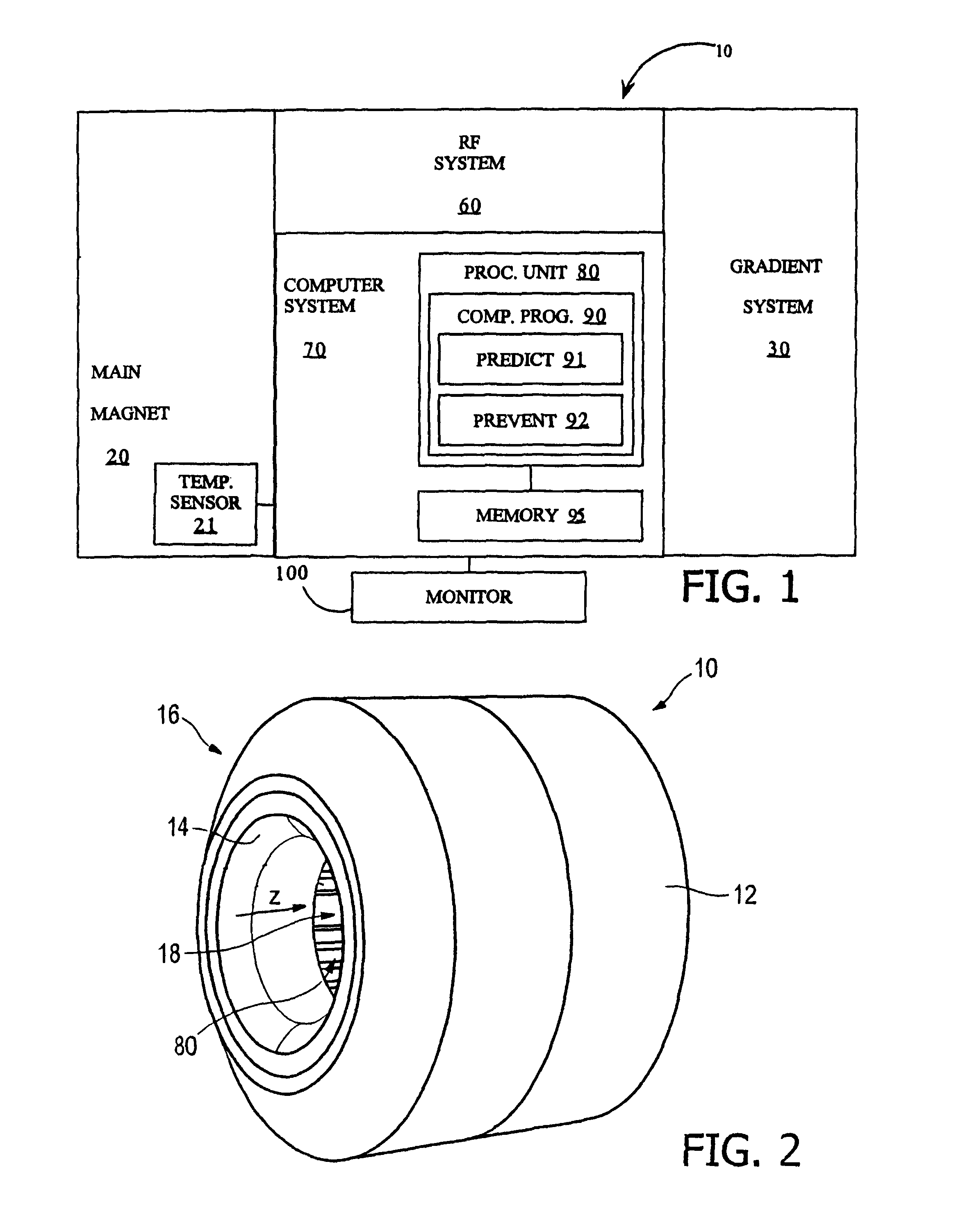
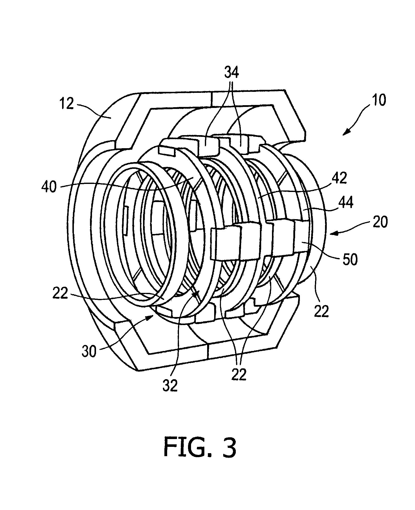
[0033]As illustrated in FIG. 1, the magnetic resonance imaging (MRI) scanner 10 comprises a superconducting main magnet 20, which surrounds an examination region 18 (see FIG. 2) and generates a main magnetic field in the examination region 18. Furthermore the MRI scanner 10 comprises a magnetic field gradient system 30 that enables spatial localization of the MRI signals. The magnetic field gradient system 30 selectively causes alternating gradient magnetic fields in the examination region 18, and is disposed outside of the main magnet 20, as described below in more detail. Furthermore the MRI scanner 10 comprises a radio frequency (RF) system 60 that transmits energy and receives signal information, and a computer system 70 to control the scanner's components and subsystems.

[0034]With reference to FIGS. 2 and 3, the MRI scanner 10 includes a housing made up of an outer flux return shield 12 and an inner bore tube 14. The outer flux return shield 12 and the inner bore tube 14 are se...


PUM


Abstract

A magnetic resonance examination system (10) includes a superconducting main magnet (20) surrounding an examination region (18) and generating a main magnetic field in the examination region (18) A magnetic field gradient system (30) selectively causes alternating gradient magnetic fields in the examination region (18). The magnetic field gradient system (30) is disposed outside of the main magnet (20). In order to provide stable operation of the superconducting main magnet (20) of a magnetic resonance examination system (10) with such a magnetic field gradient system (30), the magnetic resonance examination system (10) is provided with a predicting device (91) and a preventing device (92) The predicting device (91) predicts the behavior of the main magnet (20) due to the gradient magnetic fields (e.g., by calculating the expected heat load of the main magnet caused by an imaging protocol) and the preventing device (92) prevents, based on the predicted behavior of the main magnet (20), the main magnet (20) from quenching.

Description

FIELD OF THE INVENTION[0001]The present invention relates to a magnetic resonance examination system and to a method of operating such a magnetic resonance examination system. In particular the present invention relates to a magnetic resonance examination system comprising a superconducting main magnet surrounding an examination region and generating a main magnetic field in the examination region, and further comprising a magnetic field gradient system selectively causing alternating gradient magnetic fields in the examination region, said magnetic field gradient system being disposed outside of the main magnet.BACKGROUND OF THE INVENTION[0002]Recently, new magnetic resonance examination system designs have been proposed, in which the main magnet system comprises magnet coils of superconductive material, and in which the magnetic field gradient system is located at the outside of the superconducting coil system and a weak-iron flux conduction system is provided to guide the magneti...

Claims


Application Information

Patent Timeline
Patent Type & Authority Patents(United States)
IPC IPC(8): G01V3/00
CPCG01R33/288G01R33/3815G01R33/3804H01F6/02
Inventor TIMINGER, HOLGER
Owner KONINK PHILIPS ELECTRONICS NV
Why Eureka
Try Eureka