Hydraulic control system for vehicular power transmitting mechanism

a transmission mechanism and hydraulic control technology, applied in the direction of gearing control, gearing elements, gearing, etc., can solve the problems of reducing the power transmission efficiency of continuously variable transmission, deteriorating the durability of the belt, and the risk of an increase in the load acting on the belt, so as to achieve high durability and high energy efficiency

Inactive Publication Date: 2011-11-29
TOYOTA JIDOSHA KK
View PDF19 Cites 11 Cited by
  • Summary
  • Abstract
  • Description
  • Claims
  • Application Information

AI Technical Summary

Benefits of technology

[0007]The present invention was made in the light of the background art discussed above. It is therefore an object of the present invention to provide a hydraulic control system which has high energy efficiency and assures adequate control of the belt-tensioning pressure, transient engaging pressure and line pressure with a small number of solenoid-operated valves and high durability of the belt of the continuously variable transmission of belt-and-pulley type.
[0010]In the hydraulic control system of the present invention for the vehicular power transmitting mechanism, it is not necessary to regulate the transient coupling hydraulic pressure during the steady running of the vehicle while the frictional coupling device is held in its fully engaged state. Therefore, the line pressure can be regulated according to the second control pressure applied from the second solenoid-operated valve to the line-pressure regulating valve, while the belt-tensioning hydraulic pressure applied to the continuously variable transmission can be regulated by the first solenoid-operated valve. Accordingly, the line pressure and the belt-tensioning hydraulic pressure can be adequately regulated. Although the line pressure may rise to an unnecessarily high level in the process of the engaging action of the frictional coupling device when the speed ratio of the continuously variable transmission is relatively high, the line pressure can be adequately regulated after the frictional coupling device has been placed in the fully engaged state, so that the overall energy efficiency of the hydraulic system is significantly improved.
[0011]When the frictional coupling device is switched from its fully released state to its fully engaged state during starting of the vehicle, for example, the line pressure as well as the belt-tensioning hydraulic pressure is regulated by the first solenoid-operated valve, with the first control pressure being applied to the line-pressure regulating valve, while the transient coupling hydraulic pressure of the frictional coupling device is regulated by the second solenoid operated valve. Accordingly, an increase of the transient coupling hydraulic pressure will not cause an increase of the belt-tensioning hydraulic pressure to an unnecessarily high level, so that the durability of the belt and the power transmitting efficiency of the continuously variable transmission are improved. Although the use of the first solenoid-operated valve SLS for regulating both of the belt-tensioning hydraulic pressure and the line pressure causes an unnecessarily increase of the line pressure in the process of the engaging or coupling action of the frictional coupling device to its fully engaged state while the speed ratio of the transmission is relatively high (while the transmission is in a relatively low-gear state), this occurs only in the process of the engaging action of the frictional coupling device, and the line pressure can be adequately regulated after the frictional coupling device has been fully engaged, so that the overall energy efficiency of the hydraulic system is significantly improved.
[0012]The hydraulic control system of the present embodiment is further arranged to use the two solenoid-operated valves for regulating the belt-tensioning hydraulic pressure, the transient coupling hydraulic pressure of the frictional coupling device and the line pressure, so that the present hydraulic control system can be made more compact and smaller in size, and is available at a lower cost of manufacture, than a hydraulic control system using three linear solenoid valves for regulating the above-indicated three pressures, respectively.
[0014]In the hydraulic control system according to the above mode (2) of this invention, the control-pressure switching valve is used to not only selectively apply the first and second control pressures to the line-pressure regulating valve, but also selectively apply the coupling hydraulic pressure and the transient coupling hydraulic pressure (second control pressure) to the frictional coupling device, so that the present hydraulic control system can be made further compact, small-sized and inexpensive.

Problems solved by technology

Accordingly, when the transient coupling hydraulic pressure of the frictional coupling device is relatively high, the belt-tensioning hydraulic pressure of the continuously variable transmission may be unnecessarily high, giving rise to a risk of an increase of a load acting on the belt, consequent deterioration of durability of the belt, and reduction of power transmitting efficiency of the continuously variable transmission.
This tendency results in reduction of energy efficiency of the hydraulic system, and deterioration of fuel economy of the vehicle.

Method used


Image

  • Hydraulic control system for vehicular power transmitting mechanism
  • Hydraulic control system for vehicular power transmitting mechanism
  • Hydraulic control system for vehicular power transmitting mechanism

Examples


Embodiment Construction

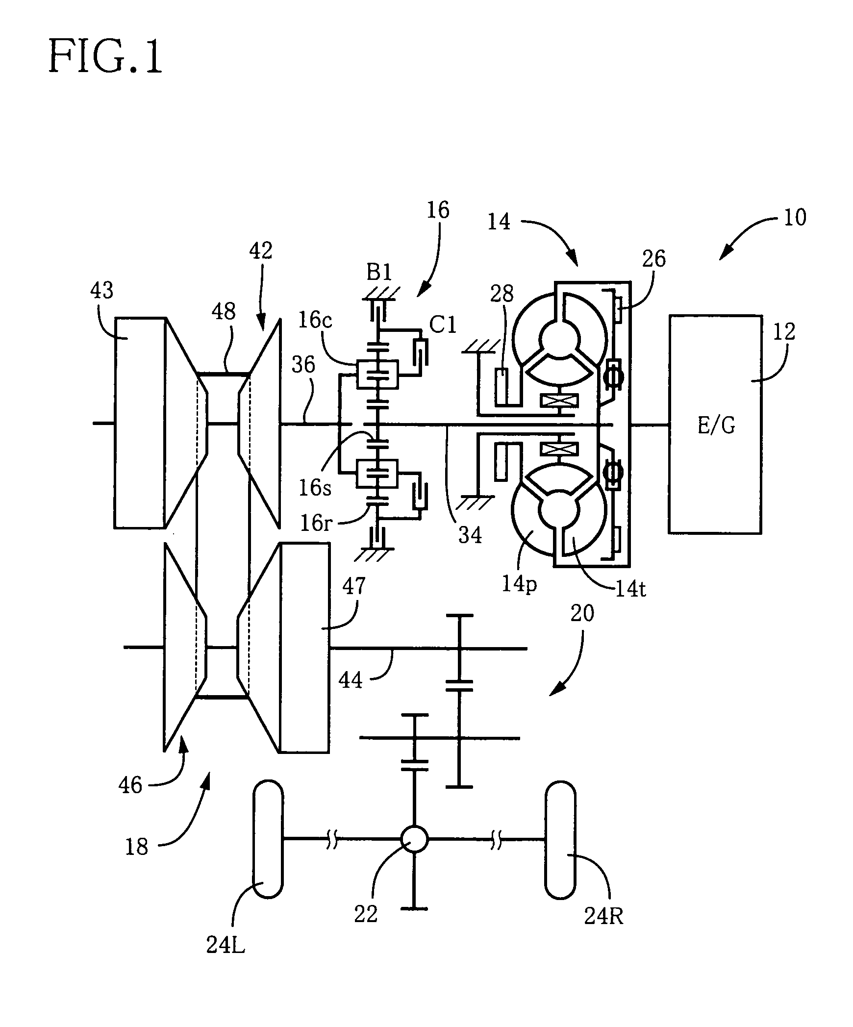
[0032]Referring first to FIG. 1, there is schematically shown a vehicular drive system 10 including a hydraulic control system constructed according to one embodiment of this invention. This vehicular drive system 10 is of a transverse type, and is suitably used for an FF type vehicle (front-engine front-drive vehicle). The drive system 10 includes a drive power source in the form of an internal combustion engine 12, a torque converter 14, a forward / reverse switching device 16, a continuously variable transmission (CVT) 18 of a belt-and-pulley type, a speed reducing gear device 20, and a differential gear device 22. An output of the engine 12 is transmitted and distributed to right and left drive wheels 24R and 24L through those devices 14, 16, 18, 20, 22. The forward / reverse switching device 16, belt-and-pulley type continuously variable transmission 18 and speed reducing gear device 20 constitute a major portion of a power transmitting mechanism.

[0033]The torque converter 14 inclu...


PUM


Abstract

A hydraulic control system for a vehicular drive system including a hydraulically operated belt-and-pulley type continuously variable transmission and a hydraulically operated frictional coupling device engaged for running of a vehicle, the hydraulic control system including: a first solenoid valve for regulating a belt-tensioning hydraulic pressure for tensioning a belt of the transmission, a second solenoid valve for regulating a transient coupling hydraulic pressure to be applied to the frictional coupling device in the process of an engaging action, a line-pressure regulating valve for regulating a line pressure used for hydraulically operated devices of the mechanism, and a hydraulic-circuit switching device operable to apply a control pressure of the second solenoid-operated valve to the line-pressure regulating valve after the frictional coupling device has been placed in a fully engaged state, and to apply a first control pressure of the first solenoid-operated valve to the line-pressure regulating valve while the frictional coupling device is in the process of the engaging action.

Description

[0001]The present application is based on Japanese Patent Application No. 2004-338166 filed on Nov. 22, 2004, the contents of which are herein incorporated by reference.BACKGROUND OF THE INVENTION[0002]1. Field of the Invention[0003]The present invention relates in general to a hydraulic control system for a vehicular power transmitting mechanism, and more particular to a hydraulic control system including two solenoid-operated valves for controlling a belt-tensioning hydraulic pressure for applying a tension to a belt of a continuously variable transmission of a belt-and-pulley type, a transient coupling hydraulic pressure of a frictional coupling device for establishing a power transmitting path, and a line pressure used for operating various hydraulically operated devices.[0004]2. Discussion of the Related Art[0005]JP-2002-181175A discloses an example of a hydraulic control system for a vehicular power transmitting mechanism including a continuously variable transmission of a bel...

Claims


Application Information

Patent Timeline
Patent Type & Authority Patents(United States)
IPC IPC(8): F16H59/00F16H63/00F16H61/26F16H7/08F16H61/662F16H61/00F16H7/22
CPCF16H61/0021F16H61/66272F16H2061/6618Y10T477/62427Y10T477/693973Y10T477/624Y10T477/6242Y10T477/693962
Inventor OGATA, YUSUKESOGA, YOSHINOBUHABUCHI, RYOJI
Owner TOYOTA JIDOSHA KK
Why Eureka
Try Eureka