
Phase delay line

a delay line and phase delay technology, applied in the field of phase delay lines, can solve the problems of different delay delays of different phase delay units, and the inability to increase or decrease the phase number by inserting or taking off delay units

Inactive Publication Date: 2011-11-29
IPGOAL MICROELECTRONICS (SICHUAN) CO LTD
View PDF9 Cites 0 Cited by
  • Summary
  • Abstract
  • Description
  • Claims
  • Application Information

AI Technical Summary

Benefits of technology

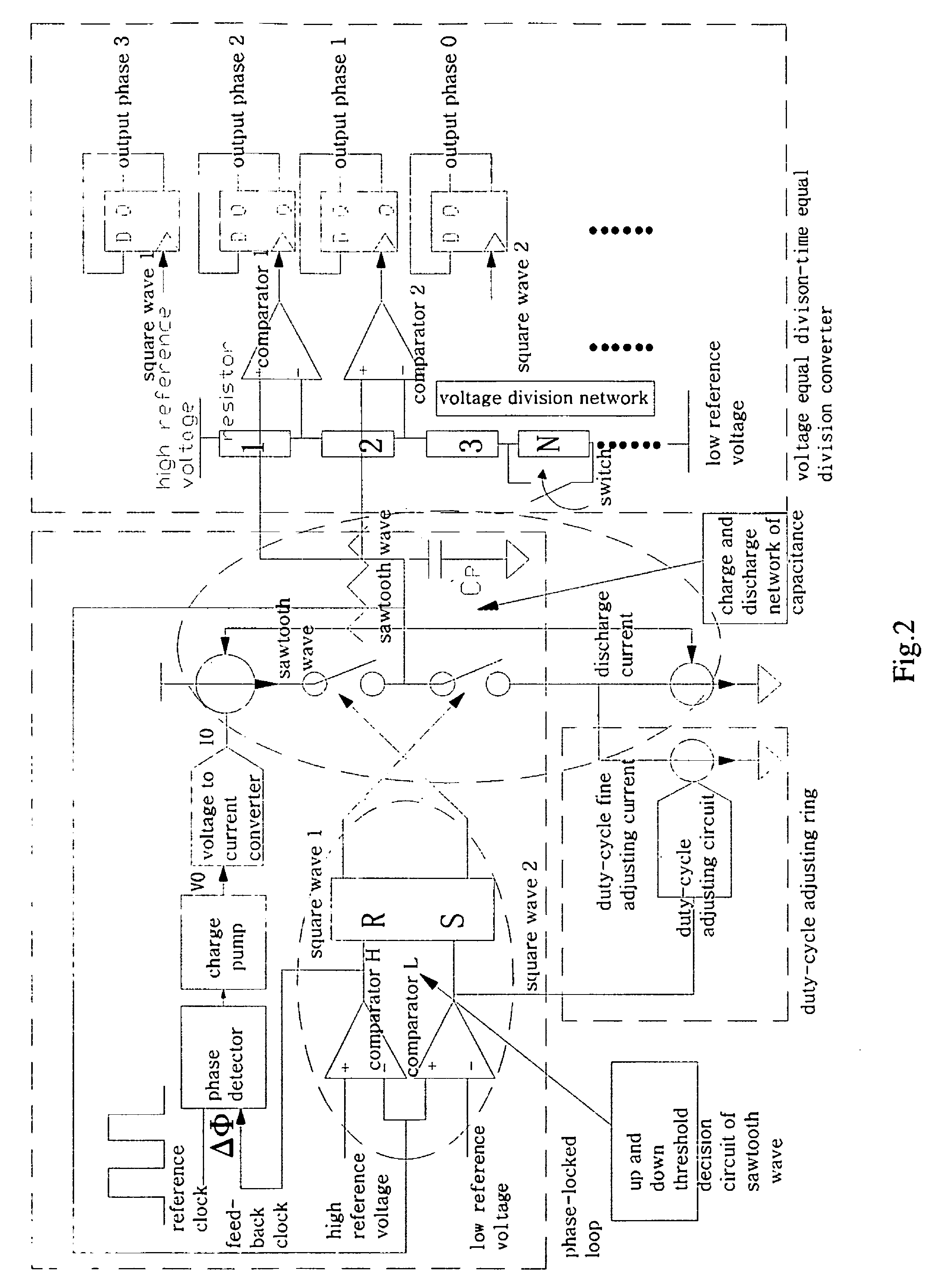
[0024]The beneficial result of the present invention is as follows.[0025]1. The most advantage of the present invention over the conventional technique is that the voltage of the sawtooth wave can be precisely divided. The equal division points are obtained from the voltage division network. Though the resistor of CMOS process has 20% error, the ratio of the resistors can be precise, so that the voltage can be equally divided. Though the circuit of the present invention, the equal division of the vertical ordinate (voltage) is converted into the equal division of the horizontal ordinate (time), because the equal division of the voltage is much easier than the equal division of the time.[0026]2. Another advantage of the present invention is that the reference clock is equally divided to n+1-phase clocks with same interval, only by setting the number of the resistors of the voltage division network as n, and the phase number can be easily controlled and expanded.[0027]3. All the reference voltage and current adopt band gap reference technology, so that the working points will not be affected by the temperature.[0028]4. The negative feedback mechanism of the phase-locked loop determines the period, phase, duty-cycle of the sawtooth wave are same with the reference clock, and will not be affected by the process and temperature.[0029]5. Because the duty-cycle adjusting circuit makes the duty-cycle of the sawtooth wave equal to that of the reference clock, which is 50%, so that the ascending and descending time of the sawtooth wave are precisely equal.[0030]6. Equal division of the voltage (high reference voltage-low reference voltage) can obtain precise delay, which is irrelevant to the absolute value of the high reference voltage and the low reference voltage.
[0026]2. Another advantage of the present invention is that the reference clock is equally divided to n+1-phase clocks with same interval, only by setting the number of the resistors of the voltage division network as n, and the phase number can be easily controlled and expanded.
[0027]3. All the reference voltage and current adopt band gap reference technology, so that the working points will not be affected by the temperature.
[0028]4. The negative feedback mechanism of the phase-locked loop determines the period, phase, duty-cycle of the sawtooth wave are same with the reference clock, and will not be affected by the process and temperature.
[0029]5. Because the duty-cycle adjusting circuit makes the duty-cycle of the sawtooth wave equal to that of the reference clock, which is 50%, so that the ascending and descending time of the sawtooth wave are precisely equal.
[0030]6. Equal division of the voltage (high reference voltage-low reference voltage) can obtain precise delay, which is irrelevant to the absolute value of the high reference voltage and the low reference voltage.

Problems solved by technology

The process ununiformity causes the mismatch between R and C, which results in the different delays of different phase delay units.
Therefore, it is impossible to increase or decrease the phase numbers by inserting or taking off delay unit.

Method used


Image

  • Phase delay line
  • Phase delay line
  • Phase delay line

Examples


Embodiment Construction

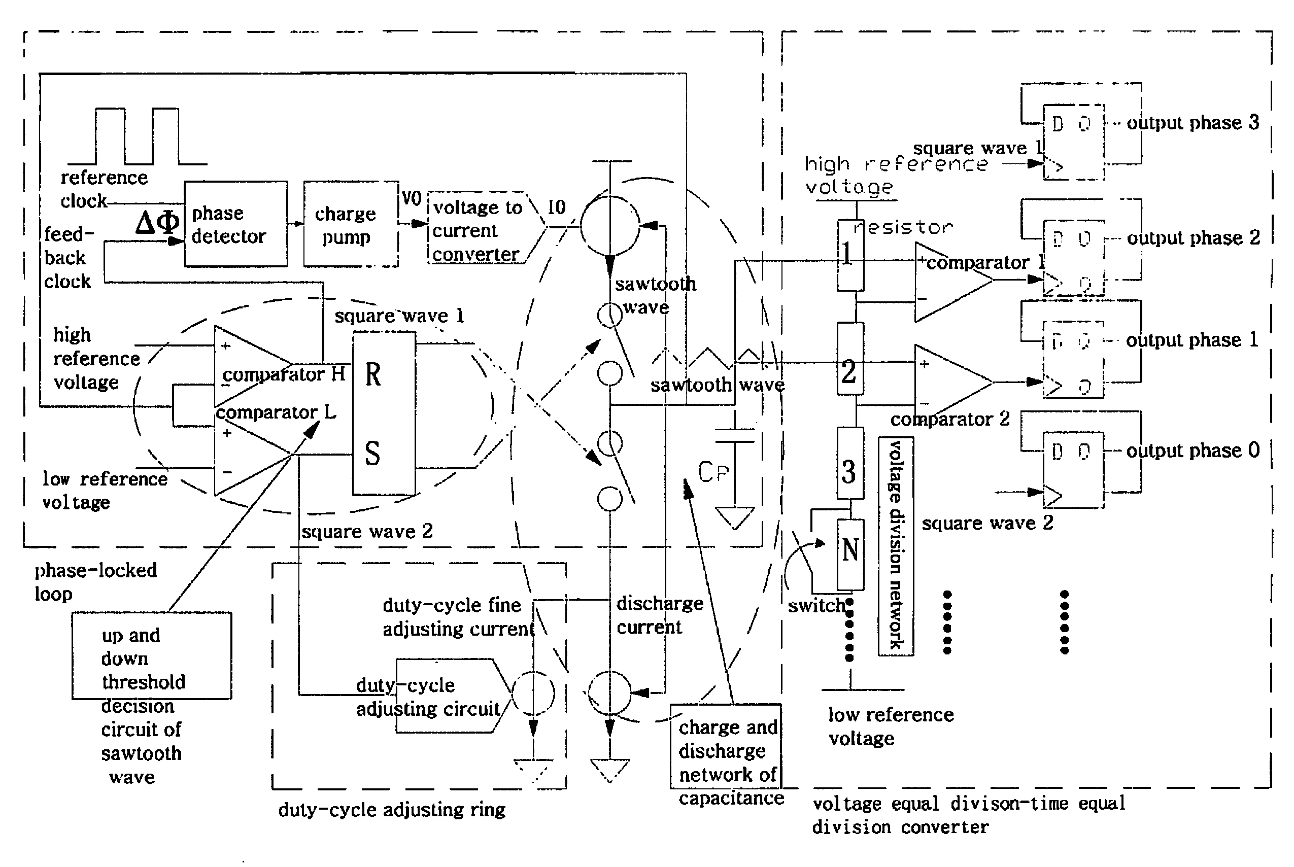
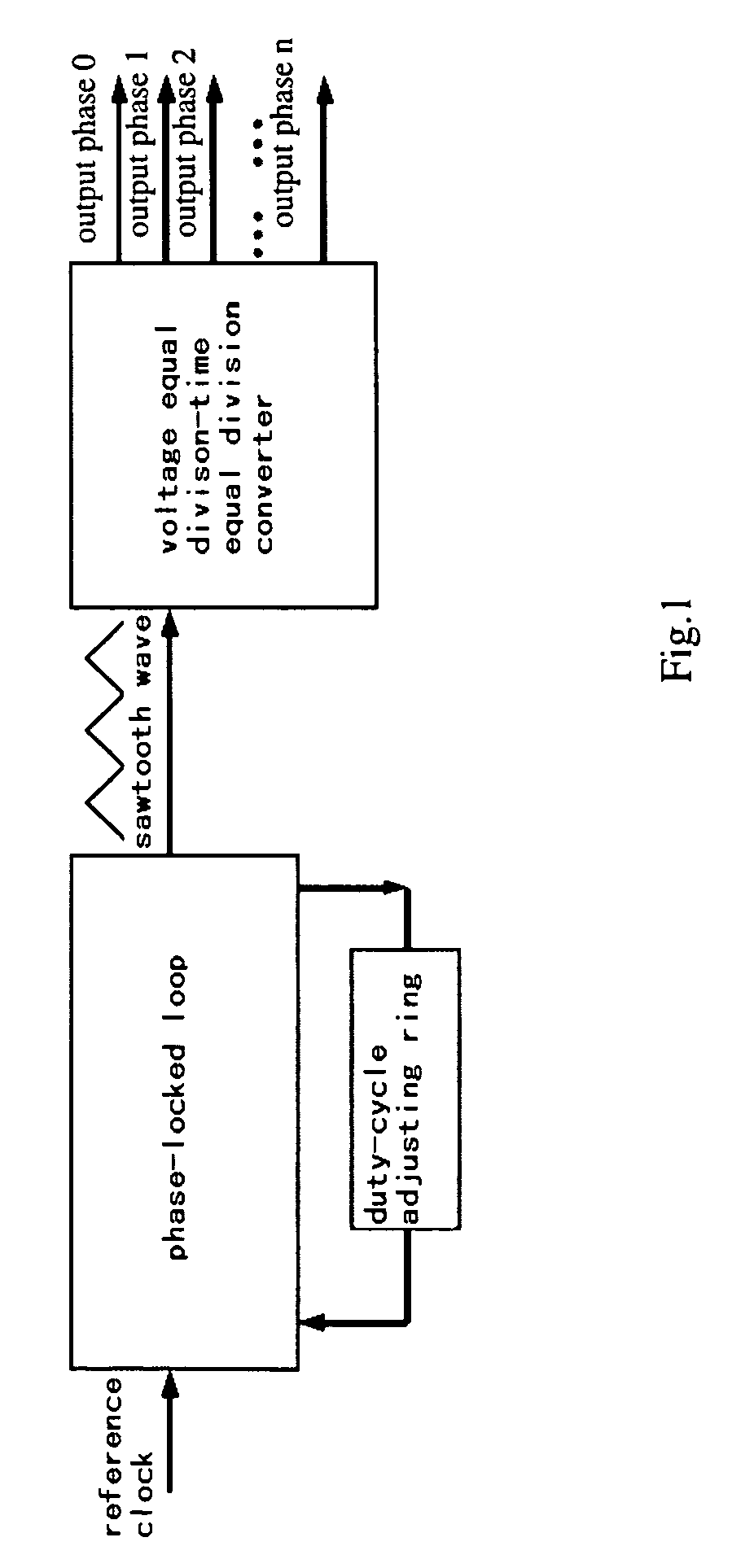
[0034]Referring to FIGS. 1 and 2 of the drawings, a phase delay line according to a preferred embodiment of the present invention is illustrated, in which the phase delay line comprises a phase-locked loop, a duty-cycle adjusting ring and a voltage-sharing to time-sharing converter, wherein the phase-locked loop and the duty-cycle adjusting ring form a loop, and one output of the phase-locked loop is connected with the input of the voltage equal division to time equal division converter.

[0035]The signal flow of the phase delay line is illustrated as follows. The reference square wave clock at about 50% duty cycle enters into the phase-locked loop. One output of the phase-locked loop is a sawtooth wave having same frequency with the reference clock, and the phase-locked loop inputs the sawtooth wave into the voltage-sharing to time-sharing converter. The voltage-sharing to time-sharing converter outputs a n-phase square wave clocks having same frequency with the reference clock and e...


PUM


Abstract

A phase delay line comprises a phase-locked loop, a duty-cycle adjusting ring and a voltage-sharing to time-sharing converter, wherein the phase-locked loop and the duty-cycle adjusting ring form a loop, and one output of the phase-locked loop is connected with the input of the voltage-sharing to time-sharing converter. The voltage can be precisely divided, and the number of the phases can be easily controlled and expanded. The band gap reference technology enables the working points not affected by the temperature. The negative feedback mechanism of the phase-locked loop determines the period, phase, duty-cycle of the sawtooth wave are same with the reference clock. The ascending and descending time of the sawtooth wave are precisely equal.

Description

BACKGROUND OF THE PRESENT INVENTION[0001]1. Field of Invention[0002]The present invention relates to integrated circuit, and more particularly to a kind of phase delay line.[0003]2. Description of Related Arts[0004]The multi-phase clock signals with the same frequency produced by the phase delay line are widely used for data acquisition. The conventional delay line mainly includes a plurality of RC delay units connected in series. The process ununiformity causes the mismatch between R and C, which results in the different delays of different phase delay units. Therefore, it is impossible to increase or decrease the phase numbers by inserting or taking off delay unit.SUMMARY OF THE PRESENT INVENTION[0005]An object of the present invention is to provide a phase delay line, which can precisely divide the reference clock into n-phases clocks of same phase interval.[0006]Accordingly, in order to accomplish the above object, the present invention provides a phase delay line including a ph...

Claims


Application Information

Patent Timeline
Patent Type & Authority Patents(United States)
IPC IPC(8): H03L7/06
CPCH03K5/13H03K5/1565H03K5/15073H03L7/099H03K5/15066H03K2005/00052H03L7/0891
Inventor ZHANG, ZICHEWU, GUOSHENG
Owner IPGOAL MICROELECTRONICS (SICHUAN) CO LTD
Learn More