SMA actuator driving device, and image pickup device incorporated with the same

a driving device and actuator technology, applied in the direction of printers, instruments, cameras focusing arrangements, etc., can solve the problems of large electric power loss of resistors, increase production costs and size, etc., and achieve the effect of suppressing electric power loss

Inactive Publication Date: 2011-11-29
KONICA MINOLTA OPTO
View PDF22 Cites 19 Cited by
  • Summary
  • Abstract
  • Description
  • Claims
  • Application Information

AI Technical Summary

Benefits of technology

[0010]In view of the above conventional examples, it is an object of the present invention to provide an SMA actuator driving device suitable for fabrication of an integrated circuit and capable of suppressing an electric power loss, and an image pickup device incorporated with the SMA actuator driving device.
[0013]In the above arrangements, there is no need of providing a high-precision resistor, which is required in using e.g. a Wheatstone bridge circuit. The above arrangements enables to constitute a constant current source of a current mirror circuit or a like element, which is advantageous in fabricating an integrated circuit, and suppressing an electric power loss.

Problems solved by technology

This may increase the production cost and the size of the SMA actuator, and cause a large electric power loss by the resistor.

Method used


Image

  • SMA actuator driving device, and image pickup device incorporated with the same
  • SMA actuator driving device, and image pickup device incorporated with the same
  • SMA actuator driving device, and image pickup device incorporated with the same

Examples


first embodiment

[0027]FIG. 3 is a block diagram showing an electrical configuration of a driving device (hereinafter, called as an “SMA actuator driving device”) 11 for driving a shape memory alloy (SMA) actuator in accordance with the first embodiment of the invention. The SMA actuator driving device 11 in the first embodiment has features that: an SMA member 7 is driven by a duty-controlled constant current to be outputted from a driving circuit 12; a detecting circuit 13 is operable to detect a voltage (hereinafter, called as a “terminal voltage”) between terminals of the SMA member 7 which is energized by the constant current; and a control circuit 14 controls the driving circuit 12 to perform a duty control in such a manner that the terminal voltage of the SMA member 7 is substantially equal to a target voltage value to be calculated based on a target resistance value and the value of the constant current. The SMA actuator driving device 11 is fabricated into an integrated circuit.

[0028]The de...

second embodiment

[0045]FIG. 7 is a block diagram showing an electrical configuration of an SMA actuator driving device 31 in accordance with the second embodiment of the invention. Elements of the SMA actuator driving device 31 substantially equivalent or corresponding to those of the SMA actuator driving device 11 are indicated with the same reference numerals, and description thereof is omitted herein. The SMA actuator driving device 31 in the second embodiment has a feature that an SMA member 7 is driven by a drive current of a variable value to be outputted from a driving circuit 32. In the above arrangement, a constant current source 20 is exclusively used for outputting a retrieval signal. The driving circuit 32 is constructed in such a manner that a switching element 36 switches over between a retrieval signal to be outputted from the constant current source 20, and a drive current to be outputted from a control circuit 34 to apply the switched current to the SMA member 7. The constant curren...

third embodiment

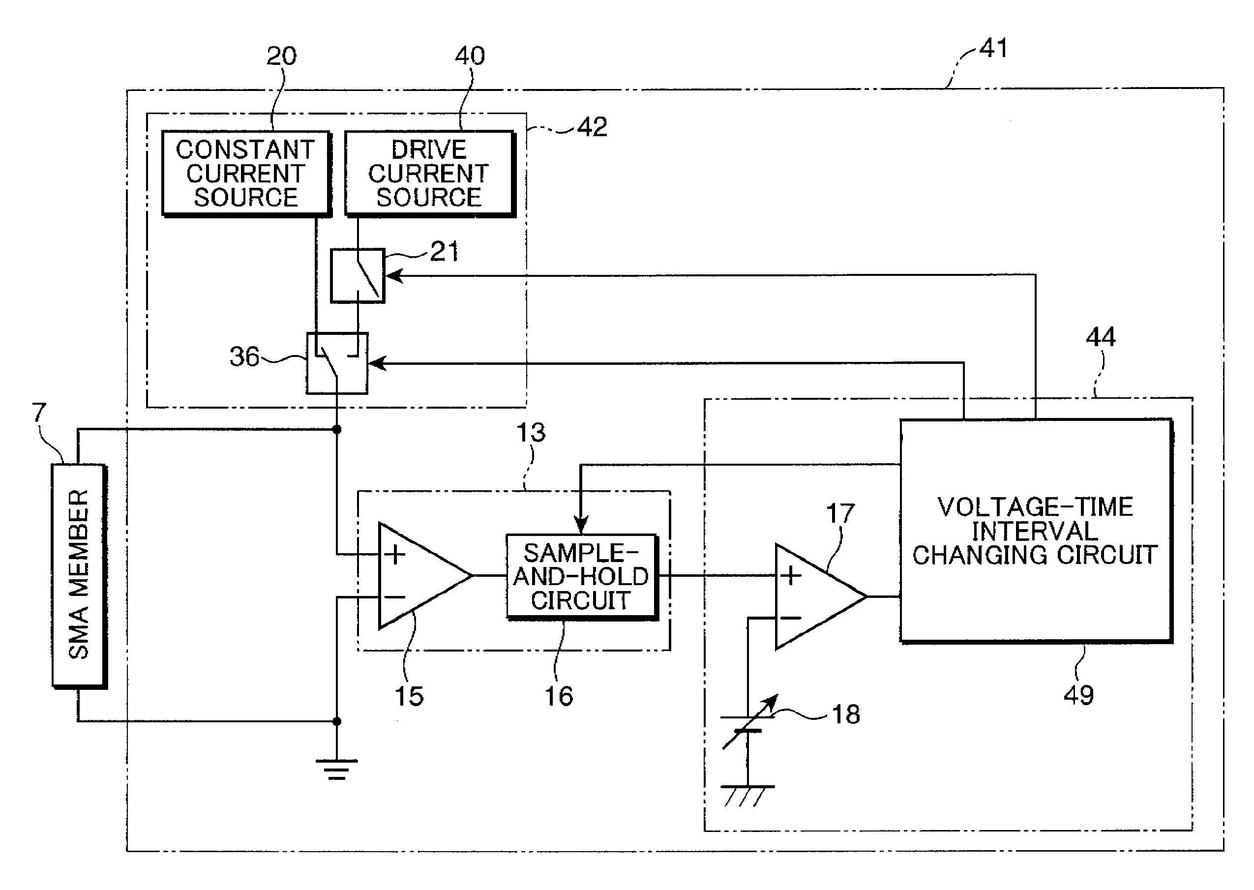
[0049]FIG. 10 is a block diagram showing an electrical configuration of an SMA actuator driving device 41 in accordance with the third embodiment of the invention. The arrangement of the SMA actuator driving device 41 is similar to the arrangement of the SMA actuator driving device 11, 31. Accordingly, elements of the SMA actuator driving device 41 substantially equivalent or corresponding to those of the SMA actuator driving device 11, 31 are indicated with the same reference numerals, and description thereof is omitted herein. The arrangement of the SMA actuator driving device 41 is different from the arrangement of the SMA actuator driving device 11, 31 in that a drive current to be applied from a driving circuit 42 to an SMA member 7 is switched over between a current, as a retrieval signal, to be outputted from a constant current source 20, and a current to be outputted from a drive current source 40 as an independent element, although a duty control is performed by a voltage-t...


PUM


Abstract

In a shape memory alloy actuator driving device, a predetermined constant current is applied to a shape memory alloy member as a retrieval signal to detect a terminal voltage of the shape memory alloy member, and a detection result of the terminal voltage is compared with a target voltage value to be calculated based on a target resistance value of the shape memory alloy member and a value of the constant current to cause a driving circuit to output, to the shape memory alloy member, a drive current that makes the detection result substantially equal to the target voltage value.

Description

[0001]This application is based on Japanese Patent Application No. 2007-177325 filed on Jul. 5, 2007, the contents of which are hereby incorporated by reference.BACKGROUND OF THE INVENTION[0002]1. Field of the Invention[0003]The present invention relates to a relatively compact image pickup device to be loaded in a camera phone or a like device; and a driving device, to be incorporated in the image pickup device, for driving a lens unit constituting an image pickup optical system for focus control or zoom control.[0004]2. Description of the Related Art[0005]In recent years, a high-resolution image pickup device has been developed. For instance, the number of pixels of an image sensor to be loaded in a camera phone or a like device has been spectacularly increased. As the high-resolution device has been developed, a high-performance lens unit constituting an image pickup optical system has also been demanded. Specifically, a fixed focal length system is replaced by an auto-focus syst...

Claims


Application Information

Patent Timeline
Patent Type & Authority Patents(United States)
IPC IPC(8): G03B13/00H04N5/232
CPCG03B3/10F03G7/065
Inventor HONDA, YASUHIROTANIMURA, YASUTAKA
Owner KONICA MINOLTA OPTO
Why Eureka
Try Eureka