
Phase dithered digital communications system

a digital communication system and phase dithered technology, applied in digital transmission, pulse position modulation, pulse automatic control, etc., can solve problems such as problems such as affecting system clocks, voltage and current spikes, and generating voltage spikes, so as to reduce receiver de-sensitization and accurate correlation with received information

Active Publication Date: 2011-11-29
QORVO US INC
View PDF25 Cites 1 Cited by
  • Summary
  • Abstract
  • Description
  • Claims
  • Application Information

AI Technical Summary

Benefits of technology

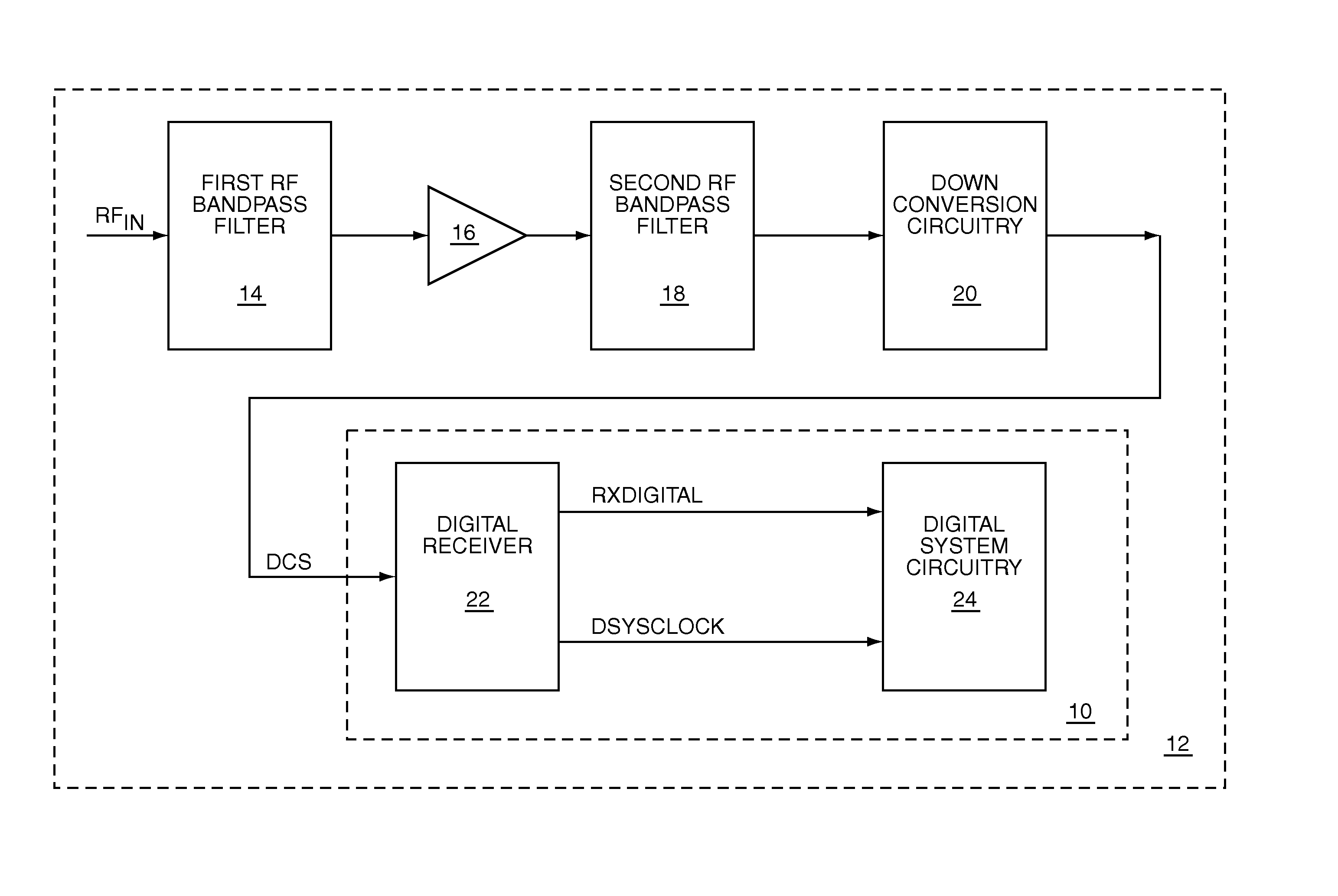
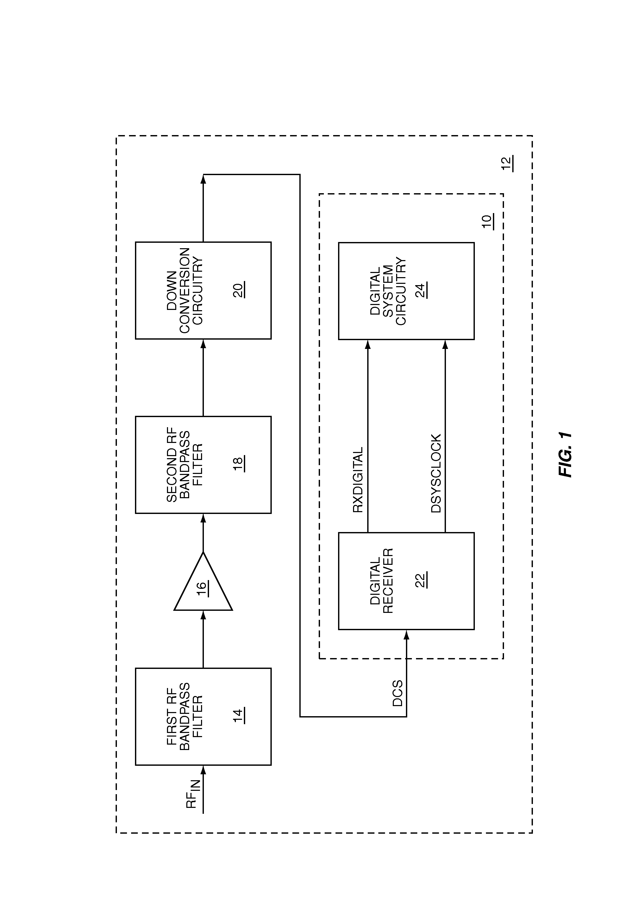
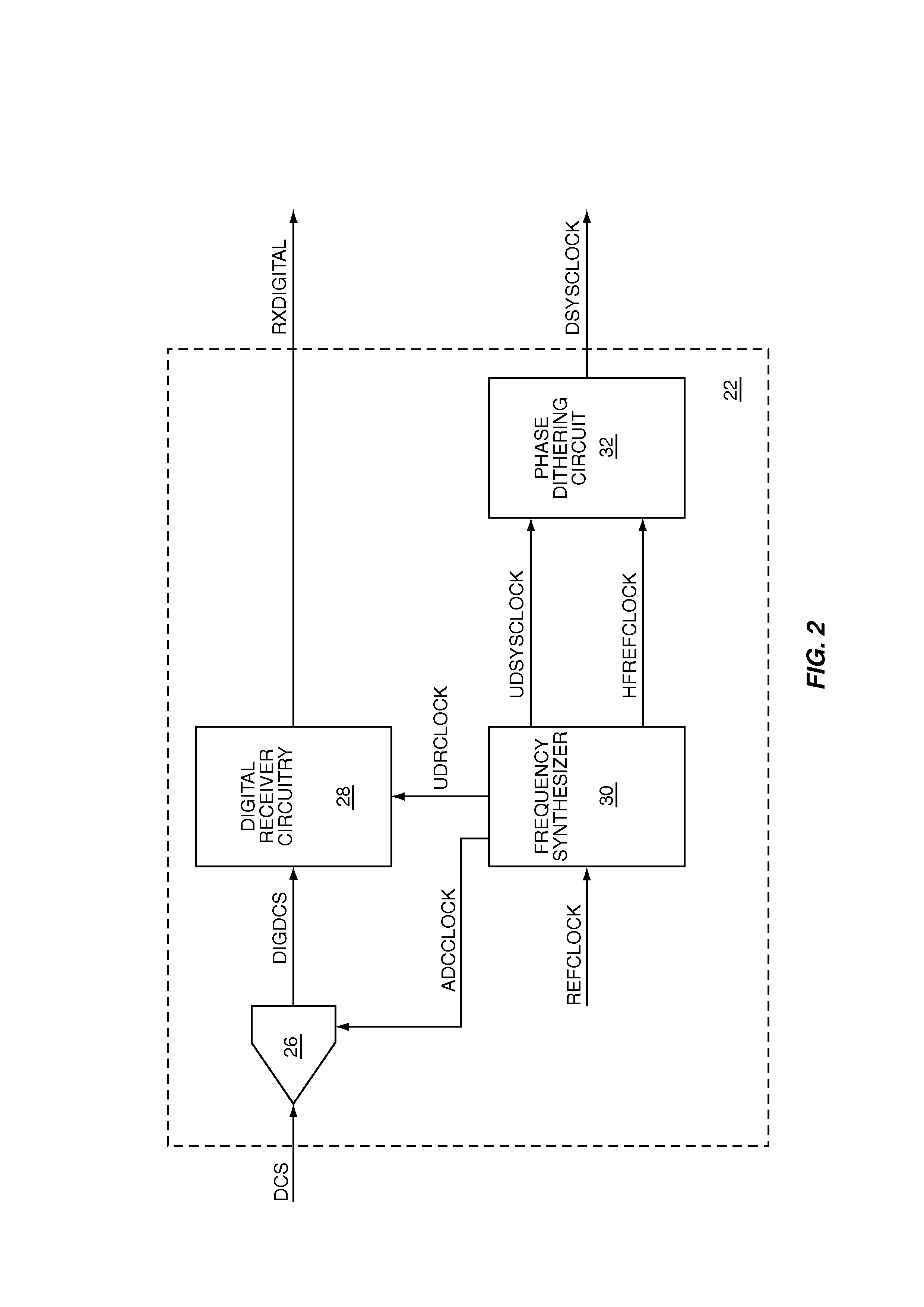
[0004]The present invention is a phase dithered digital communications system that includes a digital receiver, and uses phase dithering to spread the energy of one or more system clocks to minimize receiver de-sensitization. Phase dithering uses a single frequency for each system clock; however, the energy of each system clock is spread over a range of frequencies by changing the duty-cycle of each clock half-cycle. A non-phase dithered clock drives the sampling clock of a receiver's analog-to-digital converter to provide accurate correlation with received information. Using a non-phase dithered clock may allow use of a higher frequency sampling clock than in frequency dithered designs. Phase dithered clocks and non-phase dithered clocks may have constant frequencies that are related to each other by a ratio of two integers; therefore, the time base used for extracting received data is always correlated and accurate. The maximum error due to dithering is the phase dithering of one clock half-cycle. There is no cumulative error over time as with some frequency dithering systems.

Problems solved by technology

Digital circuitry within the system tends to transition synchronously with the system clock, which may generate voltage spikes, current spikes, or both.
The voltage and current spikes may generate interfering noise signals at the fundamental frequency and harmonics of the system clock.
Such a system may work well when receiving separated blocks of information; however, in continuous receiver types of systems, such as wideband code division multiple access (WBCDMA) systems, relating received information to the system clock may be problematic.

Method used


Image

  • Phase dithered digital communications system
  • Phase dithered digital communications system
  • Phase dithered digital communications system

Examples


Embodiment Construction

[0017]The embodiments set forth below represent the necessary information to enable those skilled in the art to practice the invention and illustrate the best mode of practicing the invention. Upon reading the following description in light of the accompanying drawing figures, those skilled in the art will understand the concepts of the invention and will recognize applications of these concepts not particularly addressed herein. It should be understood that these concepts and applications fall within the scope of the disclosure and the accompanying claims.

[0018]The present invention is a phase dithered digital communications system that includes a digital receiver, and uses phase dithering to spread the energy of one or more system clocks to minimize receiver de-sensitization. Phase dithering uses a single frequency for each system clock; however, the energy of each system clock is spread over a range of frequencies by changing the duty-cycle of each clock half-cycle. A non-phase d...


PUM


Abstract

The present invention is a phase dithered digital communications system that includes a digital receiver, and uses phase dithering to spread the energy of one or more system clocks to minimize receiver de-sensitization. Phase dithering uses a single frequency for each system clock; however, the energy of each system clock is spread over a range of frequencies by changing the duty-cycle of each clock half-cycle. A non-phase dithered clock drives the sampling clock of a receiver analog-to-digital converter to provide accurate correlation with received information, which may allow use of a higher frequency sampling clock than in frequency dithered designs. Phase dithered clocks and non-phase dithered clocks may have constant frequencies that are related to each other by a ratio of two integers; therefore, the time base used for extracting received data is always correlated and accurate.

Description

FIELD OF THE INVENTION[0001]The present invention relates to digital receivers used in digital communications systems that are part of radio frequency (RF) communications systems.BACKGROUND OF THE INVENTION[0002]RF communications systems typically use digital circuitry to provide control and data management functions, to process received and transmitted digital signals, to provide user and communication interfaces, to provide other digital functions, or any combination thereof. Such a system is typically supplied with at least one system clock that provides overall timing for the system. Digital circuitry within the system tends to transition synchronously with the system clock, which may generate voltage spikes, current spikes, or both. The voltage and current spikes may generate interfering noise signals at the fundamental frequency and harmonics of the system clock. If a frequency of an interfering noise signal falls within the passband of a received RF signal, receiver sensitivi...

Claims


Application Information

Patent Timeline
Patent Type & Authority Patents(United States)
IPC IPC(8): H04L7/00H03L7/00
CPCH03K3/84H03K7/04H04B15/06
Inventor KHLAT, NADIMSUMME, RICHARD A.HUMPHREYS, SCOTT ROBERTNGO, CHRIS
Owner QORVO US INC
Learn More