
Threaded joint for steel pipes

a technology for steel pipes and threaded joints, applied in the direction of hose connections, screw threaded joints, pipe joints, etc., can solve the problem of inability to remove threads, and achieve the effect of efficient removal of burrs

Active Publication Date: 2011-12-06
NIPPON STEEL CORP
View PDF32 Cites 6 Cited by
  • Summary
  • Abstract
  • Description
  • Claims
  • Application Information

AI Technical Summary

Benefits of technology

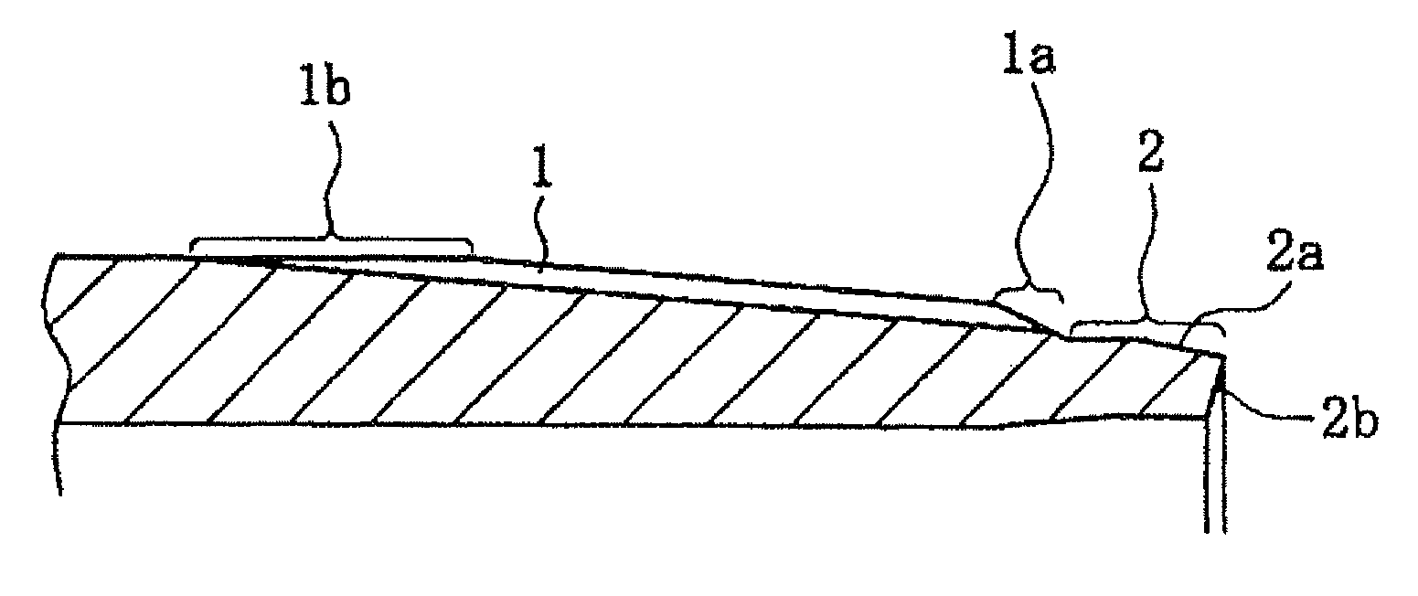
[0012]This invention provides a threaded joint for steel pipes which makes it possible to efficiently remove burrs from a beveled portion which is formed at the start of thread cutting without scratching the metal seal portion or the complete thread. Such removal was impossible in thread cutting of a conventional threaded joint for OCTG.
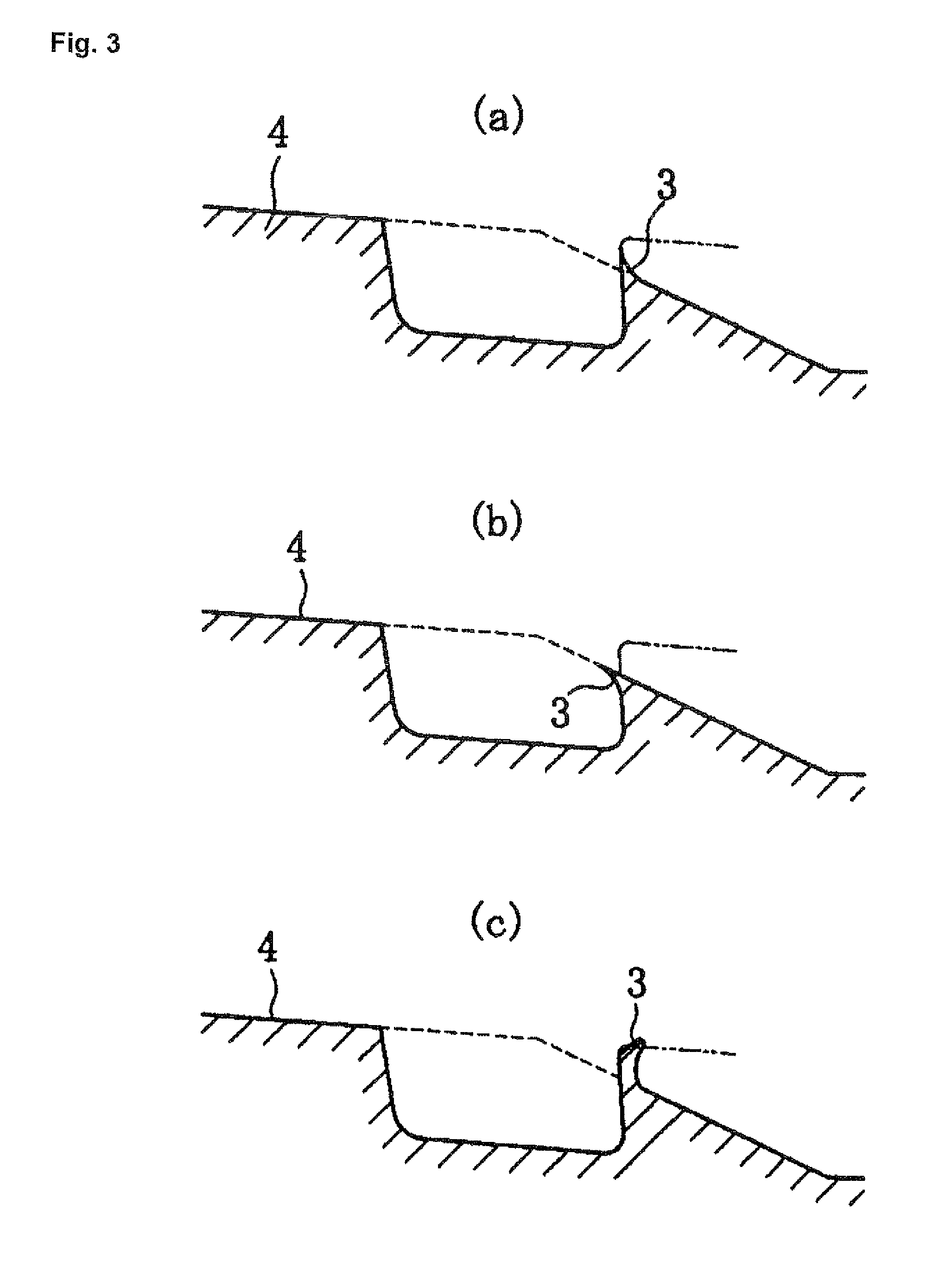
[0017]In a threaded joint for steel pipes according to the present invention, a thread having a trapezoidal shape with its crest face having a prescribed height and angle is formed by cutting off the top portion of a pointed crest of an incomplete thread typically having a beveled portion formed at the start of cutting of the male threads. This cutting off of the top portion is preferably carried out under the same feed conditions as in machine cutting of the male threads. As a result, the top portion of a thread including burrs can be efficiently cut off without scratching the metal seal portion or the complete thread, and galling at the time of makeup and breakout of OCTG using a threaded joint can be prevented.

Problems solved by technology

Such removal was impossible in thread cutting of a conventional threaded joint for OCTG.

Method used


Image

  • Threaded joint for steel pipes
  • Threaded joint for steel pipes
  • Threaded joint for steel pipes

Examples


Embodiment Construction

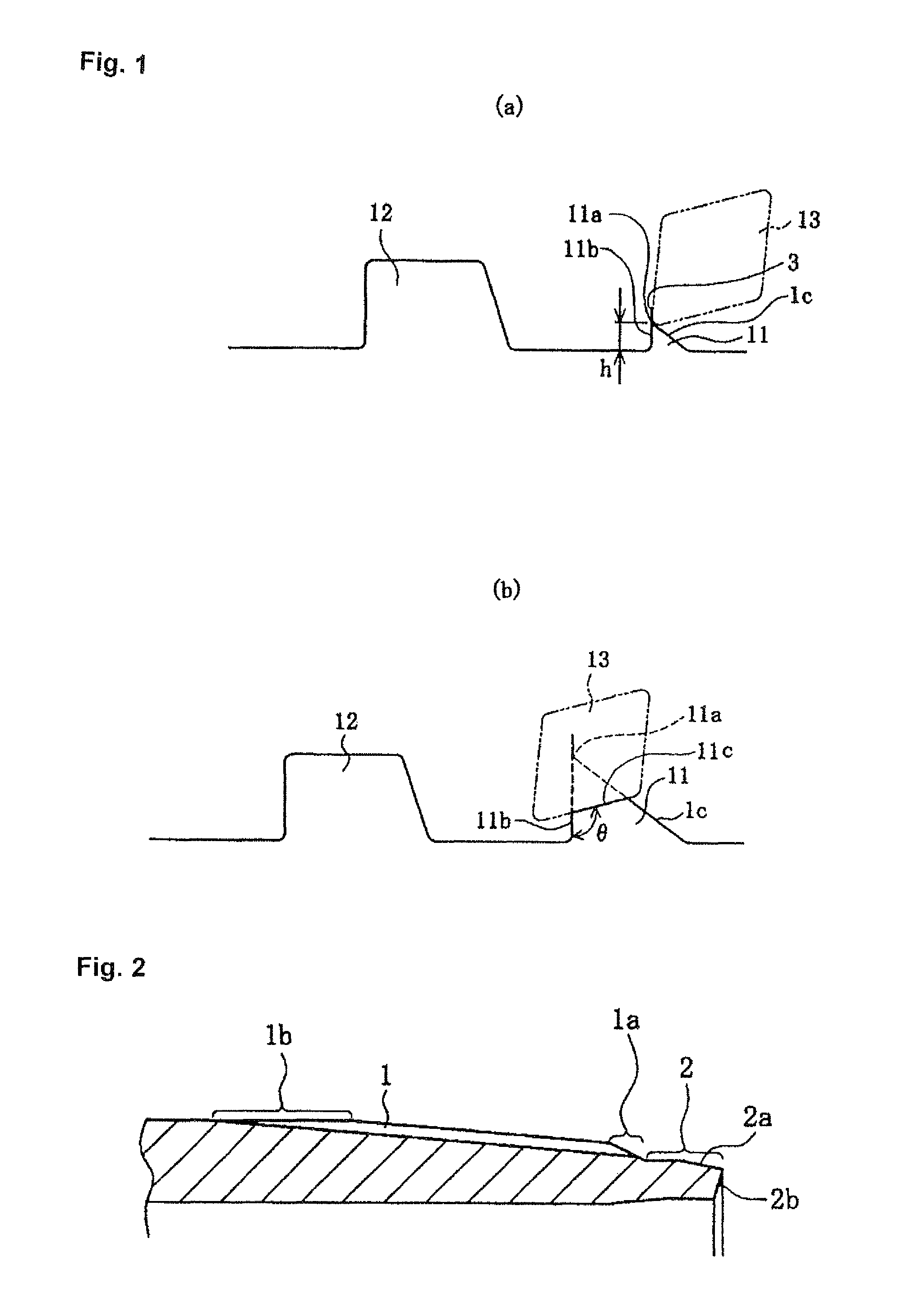
[0023]Below, a preferred embodiment of the present invention will be explained while referring to FIG. 1.

[0024]FIG. 1 is a schematic cross-sectional view showing an incomplete thread, which is an important structural feature of a threaded joint for steel pipes according to the present invention, formed at the start of cutting of tapered male threads and comparing it with a complete thread. FIG. 1(a) shows the state at the start of machining to cut off a portion of an incomplete thread with a pointed crest, and FIG. 1(b) shows the state at the completion of this machining. Since the male threads of the pin are tapered threads as stated above, the crest faces or the roots of the male threads and normally both are not parallel to the longitudinal axis of the pin but are sloping with a diameter which gradually decreases towards the tip of the pin (see FIGS. 3 and 4). However, in order to simplify the drawings, the taper is omitted from FIG. 1.

[0025]In FIG. 1, 11 is a thread (referred to...


PUM


Abstract

A threaded joint for steel pipes comprises a pin having male threads and a box having female threads which engage with the male threads. An incomplete thread is formed at the start of the male threads and the incomplete thread has a portion in which the angle θ formed between its crest face and its flank on the side facing a complete thread is an obtuse angle and in which the thread height h from the base of the flank is at least 0.2 mm.

Description

[0001]This application is a continuation of International Patent Application No. PCT / JP2008 / 056146, filed Mar. 28, 2008. This PCT application was not in English as published under PCT Article 21(2).TECHNICAL FIELD[0002]This invention relates to a threaded joint for steel pipes for connecting steel pipes such as OCTG (oil country tubular goods) used for the exploration for and production of natural gas and crude oil produced underground (beneath the surface of the land or beneath the surface of the sea). A threaded joint for steel pipes according to the present invention is particularly characterized by the thread shape of an incomplete thread which is formed at the start of cutting of tapered male threads.BACKGROUND ART[0003]OCTG used in the exploration for natural gas wells and oil wells (collectively referred to below as oil wells) and production of natural gas and crude oil are steel pipes having a length of around 10 meters. In use, they are connected to each other by threaded j...

Claims


Application Information

Patent Timeline
Patent Type & Authority Patents(United States)
IPC IPC(8): F16L15/00
CPCF16L15/001F16L15/06
Inventor FUJII, TAKASHI
Owner NIPPON STEEL CORP
Learn More