V-shaped staple for spinal prosthesis

a technology of spinal prosthesis and staple, which is applied in the direction of surgical staples, prosthesis, osteosynthesis devices, etc., can solve the problems of degenerated disc shrinkage, rupture, and prone to injury and degeneration of intervertebral discs, so as to prevent backing out of intervertebral implants and maintain stability. the effect of the intervertebral implan

Inactive Publication Date: 2011-12-06
WARSAW ORTHOPEDIC INC
View PDF4 Cites 21 Cited by
  • Summary
  • Abstract
  • Description
  • Claims
  • Application Information

AI Technical Summary

Benefits of technology

An intervertebral implant system for positioning between an upper vertebra and a lower vertebra is provided. The implant system comprises an intervertebral implant and a staple. The implant comprises an inferior plate and a superior plate, while the superior plate has a vertebral surface facing the upper vertebra and the inferior plate has a vertebral surface facing the lower vertebra. There are two grooves on at least one vertebral surface extending at an angle outward from a centerline on the vertebral surface as they extend from the anterior portion of the plate toward the posterior portion of the plate. When in use, the staple is associated with the two grooves for maintaining stability of the intervertebral implant and preventing backing out of the intervertebral implant. The staple also has two arms and has a generally rectangular shape prior to use.
The end of each arm of the staple is pointed. In some versions, the grooves are wider at the anterior portion of the plate than at the posterior portion of the plate. Also, the implant further comprises a stop situated on the anterior side of at least one of the plates such that the at least one plate does not move too far into the disc space. The implant further comprises a screw for fastening the staple into the at least one plate to which the staple is inserted. In some versions, the intervertebral implant system further comprises a second staple for fastening the staple into the other of the superior or inferior plate such that both the superior and inferior plates each have a single staple helping to maintain stability of the intervertebral implant and to prevent backing out of the intervertebral implant. With the intervertebral implant system of the present invention, it is preferred that the two grooves on the at least one vertebral surface extend at an angle outward from the centerline on the vertebral surface in the range of 10 degrees to 15 degrees from the anterior portion of the plate toward the posterior portion of the plate.

Problems solved by technology

It is known that intervertebral discs are prone to injury and degeneration.
For example, herniated discs are common, and typically occur when normal wear, or exceptional strain, causes a disc to rupture.
Degenerative disc disease typically results from the normal aging process, in which the tissue gradually looses its natural water and elasticity, causing the degenerated disc to shrink and possibly to rupture.
There are challenges, however, with dynamic implants and when there are problems, comes poor performance.
For example, maintaining the stability of dynamic implants in the disc space, or merely preventing such dynamic implants from backing-out of the disc space after they are surgically inserted are some such challenges.

Method used


Image

  • V-shaped staple for spinal prosthesis
  • V-shaped staple for spinal prosthesis
  • V-shaped staple for spinal prosthesis

Examples


first embodiment

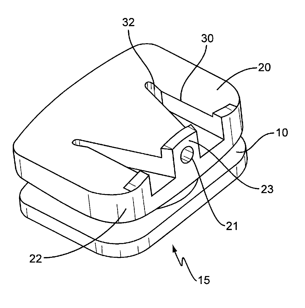
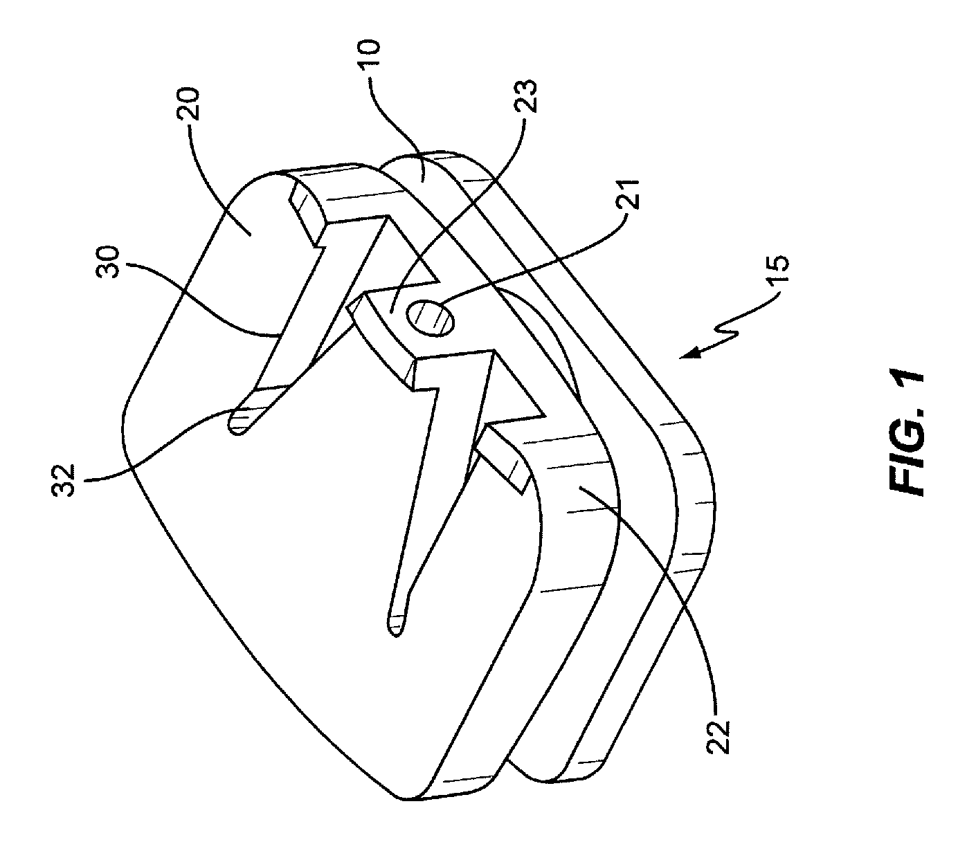
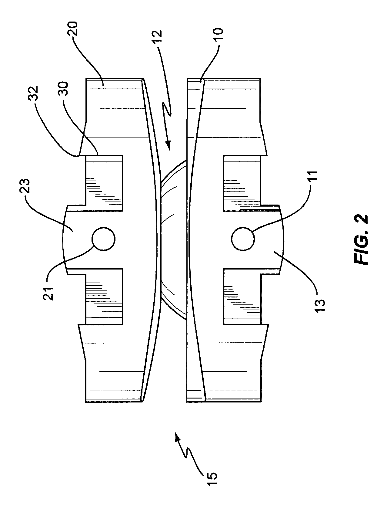
FIG. 3 shows a V-shaped staple 40, which is part of the present invention. The V-shaped staple 40 comprises two arms 44, and each arm 44 has an end 48 which is pointed (or sharp) for penetrating the endplate of each vertebrae to which the plates 10 or 20 are being affixed. The overall shape of the staple 44 before use can be described as generally rectangular. V-shaped staples of the present invention may be made from materials including titanium, titanium alloys such as nickel-titanium, stainless steel and cobalt chromium, PEEK, PEEK-carbon composites and / or any combination of the above.

second embodiment

In isometric views, FIGS. 4A and 4B demonstrate the procedure, and specifically the beginning and end stages, for implanting the V-shaped staple 40 into the superior plate 20 of the spinal implant 15 of the present invention. In FIG. 4A, the V-shaped staple 40 is introduced to the implant 15 and the vertebra (not shown). The V-shaped staple 40 can simply be hammered or power-driven through the vertebra that lies above the superior plate 20, while the V-shaped staple 40 moves through the grooves 30 and 32. That is, because of the material of the V-shaped staple 40 and the shape of the groove 30, the V-shaped staple 40 will yield to the groove 30 and change shape from a generally rectangular shape of FIG. 3 to the V-shaped staple of FIGS. 4B. That is, the angle α of each arm 44 of the V-shaped staple 40 from centerline CL (which also can be described as an angle outward from the centerline it moves from the anterior portion to posterior) is in the range of ½ degree to 15 degrees. Such...

third embodiment

A third embodiment of the present invention is illustrated and described with reference to FIGS. 3, 5, 9A, 9B, and 10. FIG. 3 shows a V-shaped staple 240, while FIG. 5 depicts an artificial disc 115 that also can be used with V-shaped staple 240. Like the first two embodiments, the V-shaped staple 240 is made of the same materials, but typically is of a smaller thickness. Specifically, for the first and third embodiments of the V-shaped staple, the preferred range of thickness is in the range of 0.3 mm. to 1.0 mm. for metal materials, and 0.5 mm. to 3.0 mm. for non-metal materials. For the second embodiment, although it can be thinner than the other embodiments, the preferred range of thickness is in the range of 0.3 mm. to 3.0 mm. for all materials. Similarly, for the first and third embodiments of the V-shaped staple, the preferred range for angle α from the centerline CL is ½ degree to 15 degrees. For the second embodiment, however, the preferred range for angle α from the center...


PUM


Abstract

An intervertebral implant system for positioning between an upper vertebra and a lower vertebra is provided. The implant system comprises an intervertebral implant and a staple. The implant comprises an inferior plate and a superior plate, while the superior plate has a vertebral surface facing the upper vertebra and the inferior plate has a vertebral surface facing the lower vertebra. There are two grooves on at least one vertebral surface extending at an angle outward from a centerline on the vertebral surface as they extend from the anterior portion of the plate toward the posterior portion of the plate. When in use, the staple is associated with the two grooves for maintaining stability of the intervertebral implant and preventing backing out of the intervertebral implant. The staple also has two arms and has a generally rectangular shape prior to use.

Description

TECHNICAL FIELDThe present invention relates generally to intervertebral implants and more particularly, to providing stability to such spinal implants when they are inserted between vertebrae to replace vertebral discs.BACKGROUNDThe human spine is a biomechanical structure with thirty-three vertebral members, and is responsible for protecting the spinal cord, nerve roots and internal organs of the thorax and abdomen. The spine also provides structural support for the body while permitting flexibility of motion. A significant portion of the population will experience back pain at some point in their lives resulting from a spinal condition. The pain may range from general discomfort to disabling pain that immobilizes the individual. Back pain may result from a trauma to the spine, be caused by the natural aging process, or may be the result of a degenerative disease or condition. Similarly, neck pain may occur in related ways, i.e., from injury, aging or disease.The intervertebral di...

Claims


Application Information

Patent Timeline
Patent Type & Authority Patents(United States)
IPC IPC(8): A61F2/44
CPCA61F2/4425A61F2/30965A61F2002/30176A61F2002/30383A61F2002/30507A61F2002/30576A61F2002/30604A61F2002/30649A61F2002/30841A61F2220/0025A61F2230/0054A61F2310/00017A61F2310/00023A61F2310/00029
Inventor YU, KIDONGDACE, MARK
Owner WARSAW ORTHOPEDIC INC
Why Eureka
Try Eureka