Control device for controlling an irradiation procedure, particle therapy unit, and method for irradiating a target volume

a control device and irradiation procedure technology, applied in the field of control devices for controlling irradiation procedures, particle therapy units, and target volume irradiation, can solve the problems of unfavorable load placed on the components of the particle therapy unit, and achieve the effect of low load on the components

Active Publication Date: 2011-12-06
VARIAN MEDICAL SYST PARTICLE THERAPY GMBH & CO KG
View PDF17 Cites 54 Cited by
  • Summary
  • Abstract
  • Description
  • Claims
  • Application Information

AI Technical Summary

Benefits of technology

[0014]The control device is operable to vary, from irradiation procedure to irradiation procedure, the sequence in which the layers are irradiated in an irradiation procedure. Large transitions or jumps in the energy of the particle beam may be avoided.
[0017]In one embodiment, the control device is designed such that the sequence of layers that are irradiated in an irradiation procedure alternates from irradiation procedure to irradiation procedure in terms of the direction of incidence. If, in a first irradiation procedure, for example, the layers are irradiated from front to back in terms of the direction of the beam, this direction is reversed in the next irradiation procedure so that the layers are now irradiated from back to front. The energy of the particle beam changes from a minimum value to a maximum value and then from the maximum value back to the minimum value. The load that is placed on components of the particle therapy unit is comparatively low.

Problems solved by technology

The adjustment of the energy may lead to an unfavorable load being placed on the components of a particle therapy unit, such as in the transition from one irradiation procedure to the next irradiation procedure, for example, if the change in energy involves large jumps.
The abrupt jump in the energy of the particle beam leads to an unfavorable load being placed on the components of a particle therapy unit.

Method used


Image

  • Control device for controlling an irradiation procedure, particle therapy unit, and method for irradiating a target volume
  • Control device for controlling an irradiation procedure, particle therapy unit, and method for irradiating a target volume
  • Control device for controlling an irradiation procedure, particle therapy unit, and method for irradiating a target volume

Examples


Embodiment Construction

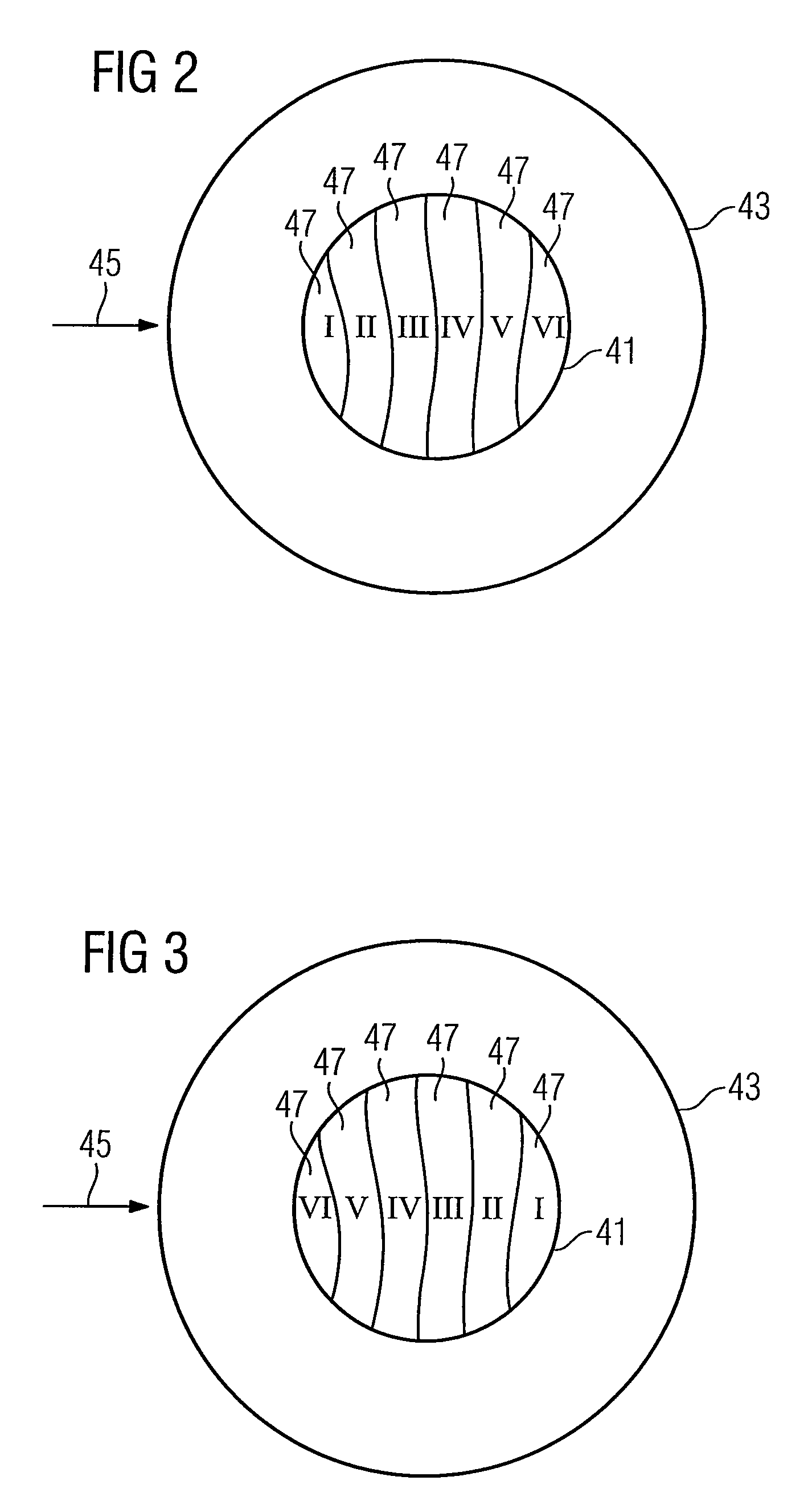
[0030]FIG. 1 shows a particle therapy unit 10. The particle therapy unit 10 is used for irradiation of a body, such as a tumor-diseased tissue, using a particle beam.

[0031]The particles may include ions, such as protons, pions, helium ions, carbon ions or other types of ions. The particles may be generated in a particle source 11. If, as shown in FIG. 1, there are two particle sources 11, which generate two different types of ions, it is possible to switch between the two types of ions within a short period of time. For example, a switching magnet 12, which is arranged between the ion sources 11 and a pre-accelerator 13 is used for switching. The particle therapy unit 10 may be operated with protons and with carbon ions at the same time for example.

[0032]The ions generated by the or by one of the ion sources 11 and optionally selected using the switching magnet 12 are accelerated in the pre-accelerator 13 to a first energy level. The pre-accelerator 13 is, for example, a linear acce...


PUM


Abstract

The present embodiments relate to a control device for controlling an irradiation procedure, which is designed in such a way that a target volume is irradiated by at least two irradiation procedures. In each irradiation procedure, an energy of a particle beam is varied in such a way that the target volume is irradiated layer-wise in layers that are spatially arranged one behind another. A sequence in which the layers of the target volume are irradiated in one of the irradiation procedures is varied from irradiation procedure to irradiation procedure, in terms of a direction of incidence of the particle beam.

Description

[0001]The present patent document claims the benefit of the filing date of German Patent Document DE 10 2007 036 035.7, filed Aug. 1, 2007, which is hereby incorporated by reference.BACKGROUND[0002]The present embodiments relate to a control device for controlling an irradiation procedure in a particle therapy unit, a particle therapy unit, and a method for irradiating a target volume.[0003]Particle therapy is used for the treatment of tissue, such as tumor diseases. Irradiation methods used in particle therapy may, however, also be used in non-therapeutic fields. The non-therapeutic fields include, for example, research work in the context of particle therapy, carried out on non-living phantoms or bodies, or irradiation of materials. In such methods, charged particles are accelerated to high energies, formed into a particle beam and directed onto an object that is to be irradiated. The particle beam penetrates the object and releases its energy in a defined location, which leads to...

Claims


Application Information

Patent Timeline
Patent Type & Authority Patents(United States)
IPC IPC(8): G02B5/00G21K1/00H01J1/52H01J29/46
CPCA61N5/10A61N2005/1087
Inventor KAISER, WERNERVAN HA.BETA.ELT, PETER
Owner VARIAN MEDICAL SYST PARTICLE THERAPY GMBH & CO KG
Why Eureka
Try Eureka