Electronic device for contention detection of bidirectional bus and related method

a bidirectional bus and electronic device technology, applied in multiplex communication, data switching networks, instruments, etc., can solve problems such as data reception failures in receivers and bidirectional bus operation failures

Active Publication Date: 2011-12-06
NOVATEK MICROELECTRONICS CORP
View PDF34 Cites 3 Cited by
  • Summary
  • Abstract
  • Description
  • Claims
  • Application Information

AI Technical Summary

Benefits of technology

[0006]The present invention therefore provides an electronic device of detecting contention of a bidirectional bus and related method that can avoid failing to output data to the bidirectional bus due to transmission collision.

Problems solved by technology

This causes an operating failure in the bidirectional bus 12.
For example, when the data signals S1 and S2 are simultaneously outputted to the bidirectional bus 12 as can be seen from FIG. 1, the transitions of the data signals S1 and S2 cause signal cancelling, thereby resulting in data reception failures in the receivers 164 and 144.

Method used


Image

  • Electronic device for contention detection of bidirectional bus and related method
  • Electronic device for contention detection of bidirectional bus and related method
  • Electronic device for contention detection of bidirectional bus and related method

Examples


first embodiment

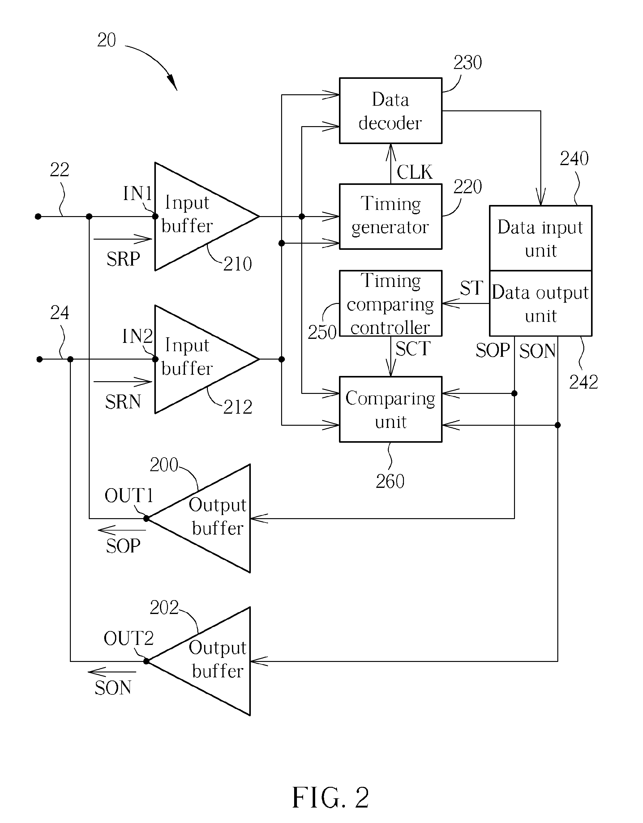
[0019]Please refer to FIG. 2, which is a schematic diagram of an electronic device 20 according to the present invention. In this embodiment, the electronic device 20 is installed in a slave device and responsible for detecting bus contention on bidirectional links 22 and 24 of a half-duplex bidirectional bus. The electronic device 20 includes output terminals OUT1 and OUT2, input terminals IN1 and IN2, output buffers 200 and 202, input buffers 210 and 212, a timing generator 220, a data decoder 230, a data input unit 240, a data output unit 242, a timing comparing controller 250 and a comparing unit 260. The input terminals IN1 and IN2 are adapted to receive data reception signals SRP and SRN from the bidirectional links 22 and 24 respectively. The input buffers 210 and 212, both preferably a Schmitt trigger, determine signal levels of the data reception signals SRP and SRN according to a plurality of predetermined signal levels for signal equalization. The signals transmitted on t...

second embodiment

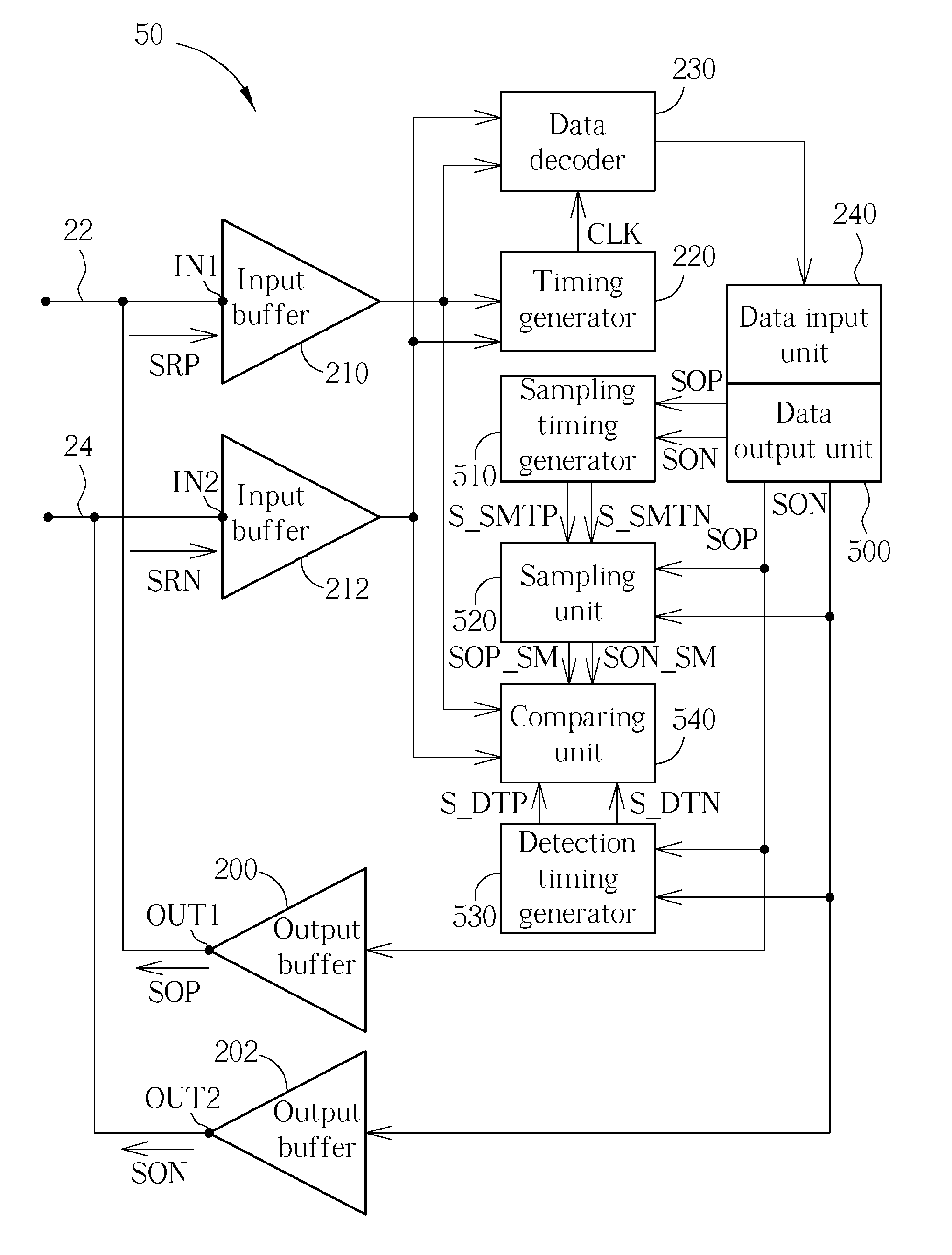
[0031]Please refer to FIG. 5, which is a schematic diagram of an electronic device 50 according to the present invention. Parts of elements in the electronic device 50 are identical with the corresponding elements in the electronic device 20, and thereby the associated detailed descriptions about operations are omitted. The electronic device 50 is also used for detecting contentions of the bidirectional links 22 and 24 and includes output terminals OUT1 and OUT2, input terminals IN1 and IN2, output buffers 200 and 202, input buffers 210 and 212, a timing generator 220, a data decoder 230, a data input unit 240, a data output unit 500, a sampling timing generator 510, a sampling unit 520, a detection timing generator 530 and a comparing unit 540. The data output unit is used for providing the data output signals SOP and SON for the sampling timing generator 510, the sampling unit 520, and the detection timing generator 530. The sampling timing generator 510 generates a sampling timin...


PUM


Abstract

An electronic device of detecting contention of a bidirectional bus for avoiding failing to drive a bidirectional bus due to bus contention includes: an output terminal, an input terminal and a data output unit, a timing comparing controller and a comparing unit. The output terminal is coupled to the bidirectional bus and used for outputting a data output signal to the bidirectional bus. The input terminal is coupled to the output terminal and the bidirectional bus and used for receiving a data reception signal from the bidirectional bus. The data output unit is used for providing the data output signal. The timing comparing controller is used for generating a timing comparison signal according to the data output signal. The comparing unit is used for comparing the data reception signal with the data output signal according to the timing comparison signal to determine a contention state of the bidirectional bus.

Description

BACKGROUND OF THE INVENTION[0001]1. Field of the Invention[0002]The present invention relates to an electronic device and related method for detection of bus contention, and more particularly, to an electronic device of detecting contention of a bidirectional bus and related method.[0003]2. Description of the Prior Art[0004]A bus is a transmission interface capable of transmitting data between two electronic devices or among a plenty of electronic devices. In general, buses are classified with unidirectional and a bidirectional types. The unidirectional bus is allowed to transmit data from an X device to a Y device, but not from the Y device to the X device. The bidirectional bus is allowed to exchange data between the X and Y devices. In implementation of a chip, employment of the bidirectional bus interface has a need of fewer pins than employment of the unidirectional bus.[0005]Please refer to FIG. 1, which is a schematic diagram of a master-slave system 10 according to the prior...

Claims


Application Information

Patent Timeline
Patent Type & Authority Patents(United States)
IPC IPC(8): G06F13/00H04L12/413H04L12/43
CPCG06F13/376
Inventor LIN, CHING-CHUNLIU, SHANG-I
Owner NOVATEK MICROELECTRONICS CORP
Why Eureka
Try Eureka