Double-layer cable-strut roof system

a cable-strut roof and double-layer technology, applied in the direction of building roofs, building reinforcements, construction, etc., can solve the problems of high cost, complicated prestressed structure, heavy structure, etc., and achieve the effect of facilitating description and stable self-equilibrium

Active Publication Date: 2011-12-13
XUE GUIBAO
View PDF3 Cites 4 Cited by
  • Summary
  • Abstract
  • Description
  • Claims
  • Application Information

AI Technical Summary

Benefits of technology

[0011]An object of the present invention is to provide a double-layer cable-strut roof structure with rational forces transmission and without strong peripheral and lower supporting system by applying the tensegrity principle. The structure overcomes the disadvantages and shortcomings of the rigid reticulated shell structure, prestressed flexible structure and cable dome structure, having the advantages of tensegrity structure such as stable self equilibrium in the self-stress state, lightweight, independence, which can be applied in exhibition venue, stadium, theater, airport terminal, railway station and other large-span space structures. More specifically, the invention of the double-layer cable-strut roof system includes a central structure, an edge structure and an intermediate structure between them. The intermediate structure comprises a plurality of cable-strut units constructed of a plurality of tension members and compression members arranged in the predefined manner, in which tension members form a continuous network and compression members are discontinuous or continuous, each node receiving a plurality of tension members but only one or two compression members. In order to facilitate the description, each node receiving only one compression member within intermediate structure is named as a first system, otherwise as a second system.
[0013]The way forces distributed within the first system is similar to that within tensegrity structure. The topology of the first system is predefined, each node receiving a plurality of cables and a single strut (a plurality of struts only in the central and edge structures). The first system is independently of the external supporting system, during assembling the components and the nodes, tension in cables and compression in struts being established by interaction of cables, struts and nodes. When each node is in equilibrium between tension and compression, which is in a self equilibrated state, all cables are in tension and all struts are in compression, the whole system being in a stable self equilibrated state. The roof system of the invention, placed on the ground or hoisted to a hanging position such as top of support columns or other lower supporting structure, is independent of the external around or down below supporting system and an independent structure after assembling. So the cable-strut roof system is a self-equilibrium system, which makes essential difference from prestressed system anchored to an external supporting system. Furthermore, the invention of the first system utilizes the way of transmitting forces of continuous tension and discontinuous compression, and efficiently uses the material characteristics of high tensile strength of cable and the compressive strength of strut to make the structure with rational forces distribution, low cost and lightweight. Thus, the invention of the double-layer cable-strut roof system overcomes the disadvantages and shortcomings of the above mentioned Geiger system and Levy system, which rely on a strong external supporting system, and has the advantages what tensegrity structure has. Moreover, as the topology of the system is predefined, the forces are evenly distributed within the system. Thus, as the span increases, the size of components has little change, so that steel consumption and dead weight of the structure substantially increase in proportion to the span to achieve a more large-span structure. Moreover, in practical projects, the less variety of nodes and component specifications can be used to allow for low cost and industrialization.
[0015]The central and the edge structures may also utilize cable-strut structure so as to bring great convenience for fabrication and assembling of structural components. The diagonal struts, cables, compression rings and tension-compression rings are arranged in a manner with specified topology of structural components, so the values of compression in the compression rings, in the tension-compression rings and in the diagonal struts belong to a same level. The struts specifications used in the compression rings, in the tension-compression rings and in the diagonal struts could be same without huge reinforced concrete rings or prestressed concrete rings so as to greatly simplify the structural design and assembling construction to allow for low cost and industrialization.
[0017]The above mentioned second system of the cable-strut roof system has the advantages not only of what the first system has, such as no need to be anchored to an external supporting system, self-stress, self-equilibrium, rational and uniform forces distribution within the system, etc., but also of lower cost. As the second system is in continuous tension and continuous compression, which is different from the first system that is in continuous tension and discontinuous compression so as to have a lower steel consumption compared with the first system.
[0019]Compared with the central and the edge structures comprising cable-strut structures in the first system, the central and the edge structures in the second system comprise a simpler structure to bring a greater convenience for structural designing, component fabrication, construction and installation.

Problems solved by technology

The structure is heavyweight and more expensive to build with increasing in span.
The boundary and lower supporting system can only be designed firmly for equilibrating internal tension forces, leading to high cost and a complicated prestressed structure.
Another disadvantage of flexible structures involves too large structural deformation under loading.
But, so far, with the exception of some tensegrity sculpture having the characteristics of art, tensegrity structure hasn't been used in buildings of large-span roof system in the field of construction.
However, this structure does not use triangulated construction, so the structure lacks a degree of lateral stability at the top radial chord of the dome.
Furthermore, due to the radial arrangement of the vertical strut, this structure is only appropriate for use in circular plane.
Moreover the compression ring has been a part of the whole building, it is very difficult to identify cable dome structure as an independent structure.
As the Geiger system and the Levy system rely on a robust supporting system around and down below, they are still in the scope of prestressed structures and will inevitably have disadvantages of prestressed structure.
Furthermore, such domes are costly to build due to node fabrication, construction and installation.

Method used


Image

  • Double-layer cable-strut roof system
  • Double-layer cable-strut roof system
  • Double-layer cable-strut roof system

Examples


Embodiment Construction

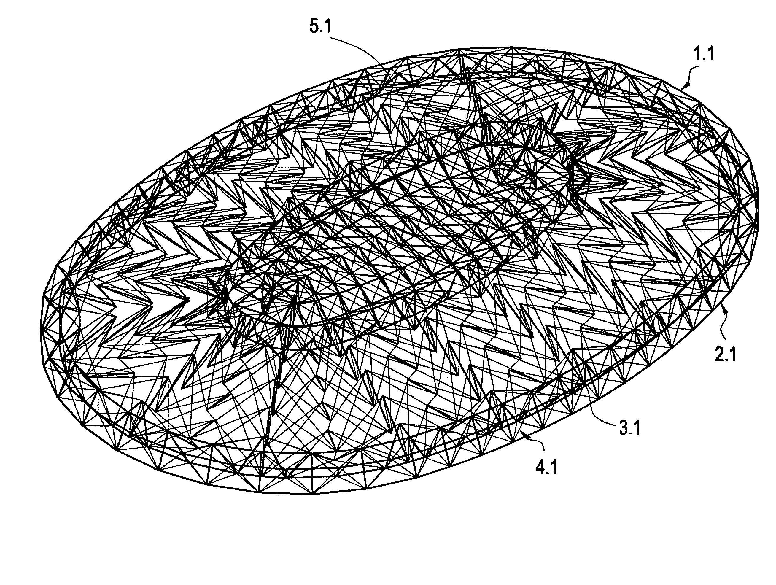
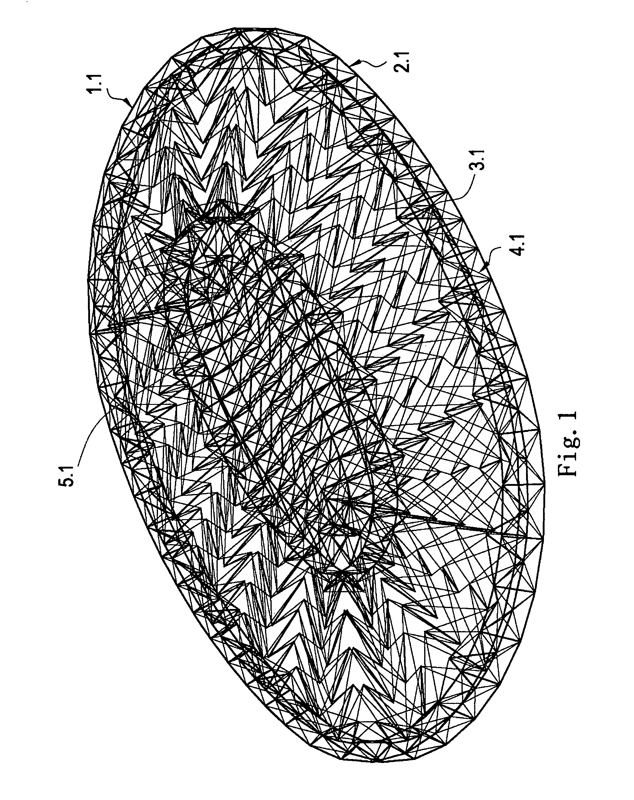
[0069]Referring to FIGS. 1 to 23, a double-layer cable-strut roof system according to preferred embodiments of the present invention is illustrated.

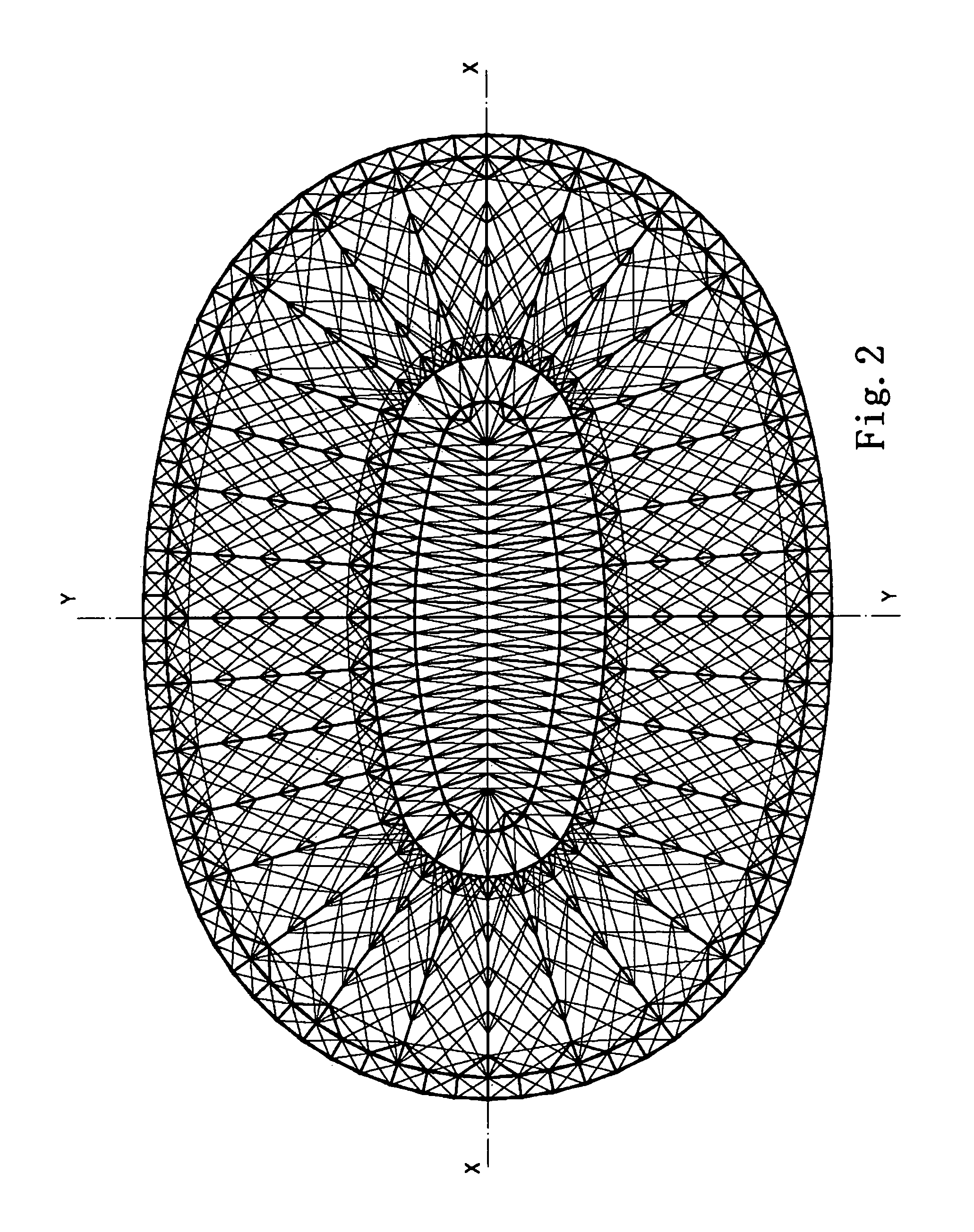
[0070]FIG. 1 is a perspective view of a double-layer cable-strut roof system in accordance with one embodiment of the first system of the present invention. It is to be noted that structural members are arranged regularly in the system but people skilled in the art will understand after reading the description that the system can be constructed in various manners with irregular structural members' arrangement. An upper layer 1.1 of the roof system may cover entirely or partially roofing materials space as required. In this embodiment of the present invention, a lower layer 2.1 is parallel to the upper layer 1.1, but they may not parallel each other. A plurality of diagonal struts 3.1, diagonal cables 4.1 and vertical cables 5.1 are arranged between the upper and the lower layers. Plan views of the upper and the lower layers, layout drawi...


PUM


Abstract

A double-layer cable-strut roof system includes a central structure and an edge structure, a plurality of sets of first diagonal struts and a plurality of sets of second diagonal struts provided between the two structures, each set of first diagonal struts being arranged alternately with one set of second diagonal struts. Or a plurality of sets of diagonal struts are provided between the two structures, each of which including a plurality of first diagonal struts and second diagonal struts joined together node to node, each first diagonal strut being arranged alternately with one second diagonal strut The roof structure may cover the underlying building space in its entirety or, alternatively, may cover a perimeter portion of the building space leaving the center area uncovered, or may be constituted by a plurality of structural units, which is adapted for spanning large areas devised for a wide range of building shapes.

Description

BACKGROUND OF THE PRESENT INVENTION[0001]1. Field of Invention[0002]The present invention relates to a cable-strut roof system, and more particularly to a double-layer cable-strut roof system which comprises a plurality of tension members and compression members arranged in a new manner, and is adapted for exhibition venue, stadium, theater, airport terminal, railway station and other large-span space structure buildings.[0003]2. Description of Related Arts[0004]In recent decades, various types of large-span roof systems are widely used, such as reticulated shell structure constructed of rigid structural members. Reticulated shell structures, however, exhibit high ratio of rise to span, in order to obtain necessary stiffness and good work performance. The structure is heavyweight and more expensive to build with increasing in span.[0005]Lightweight roof structures have gradually been applied with the development of new materials and new technology, such as application of prestressed...

Claims


Application Information

Patent Timeline
Patent Type & Authority Patents(United States)
IPC IPC(8): E04B7/14
CPCE04B7/14E04B2001/1996E04B1/342
Inventor ZHANG, LI
Owner XUE GUIBAO
Why Eureka
Try Eureka