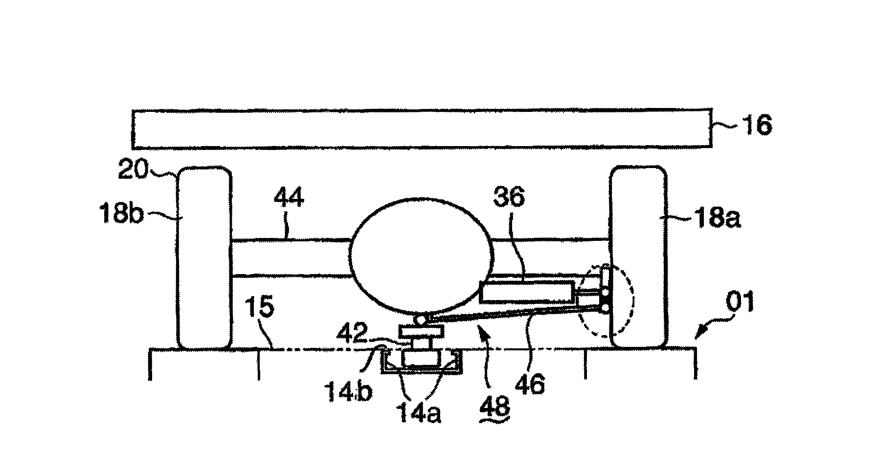
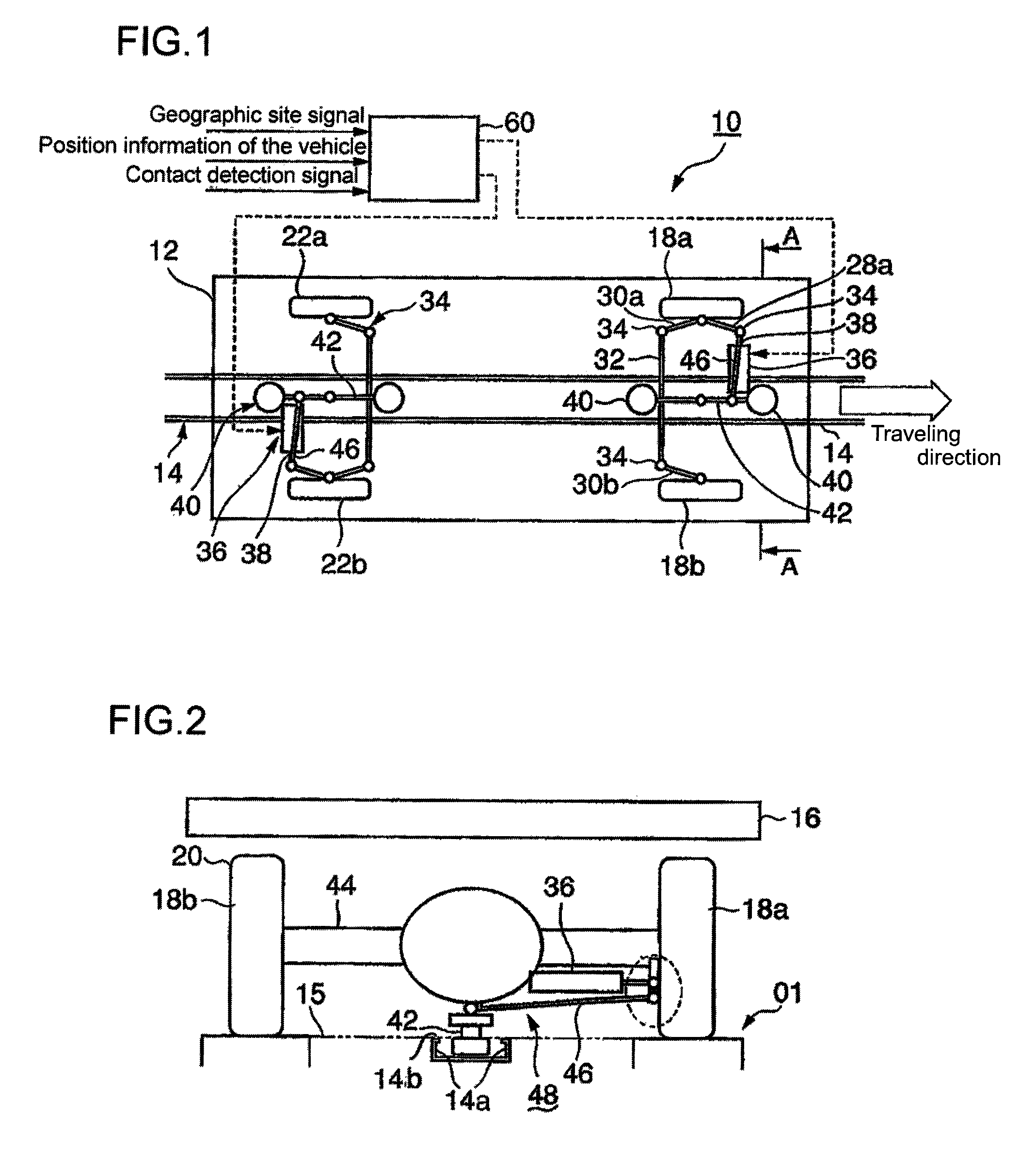
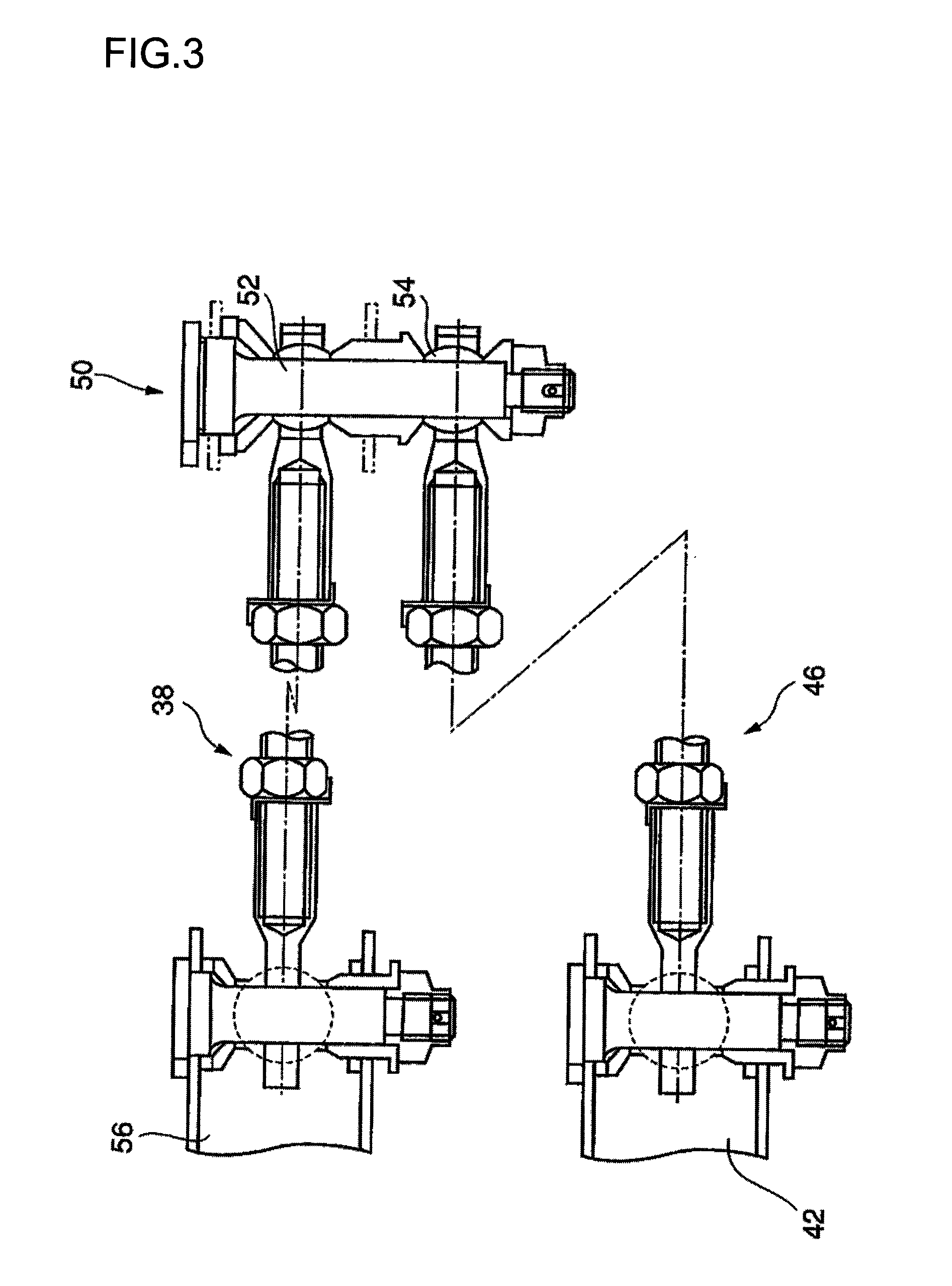
Structure of bifurvation and crossover site of guideway in guided vehicle transportation system

a technology of vehicle transportation system and guideway, which is applied in the direction of routes, rope railways, locomotives, etc., can solve the problems of increased guideway construction cost, increased running cost, and inability to solve, and achieve the effect of ensuring smooth vehicle travel

Active Publication Date: 2011-12-13
MITSUBISHI HEAVY IND ENG LTD
View PDF37 Cites 17 Cited by
  • Summary
  • Abstract
  • Description
  • Claims
  • Application Information

AI Technical Summary

Benefits of technology

[0023]The present invention was made in light of the background as mentioned above, and the object of the invention is to secure smooth travel of the vehicle at a bifurcation or crossover site of the guideway by eliminating the problems mentioned above that occurs when the vehicle passes the portion where the guard rail crosses the roadbed and to secure smooth switching of connection of the groove of the guard rail to an intended groove of the guard rail at a branching part thereof in a guided vehicle transportation system in which a fail-safe mechanism is constituted by the automatic steering mechanisms provided to the vehicle, guard wheels supported underside the vehicle, and guard rail laid down on the guideway.

Problems solved by technology

The mechanical guide mechanism is superior in point of view of safety and reliability, however, structure of bogies to which the wheels and driving mechanism thereof are mounted becomes complicated inevitably, is increased in weight, and results in increased running costs.
Further, it is necessary to lay down the guard rail having enough strength to support the guide wheels all along the guideway with high accuracy, which results in increased construction costs of the guideway.
However, according to the automatic steering system disclosed in the patent literature 1, mechanical steering by means of the guide rail and guide wheels is not performed, and a problem of securing safety of vehicle traveling against runaway and running out of track when malfunction occurs in the steering system and under abnormal circumstances caused by strong wind, rainfall, snowfall, etc. has not been solved.
However, in the guided vehicle transportation system provided with the fail-safe mechanism as mentioned above, there are inevitably bifurcation site or crossover site such as Y-shaped fork roads or X-shaped fork roads, where guard rail diverges into two or more guard rails.
When the width of the opening of the groove of the guard rail is wide as mentioned above, tires of the traveling wheels may fall into the groove or be bitten into the opening of the groove when passing over the guide rail, suffer injury, and vibration occurs which deteriorate ride quality.
Further, there is a possibility that the guard rail is damaged.

Method used


Image

  • Structure of bifurvation and crossover site of guideway in guided vehicle transportation system
  • Structure of bifurvation and crossover site of guideway in guided vehicle transportation system
  • Structure of bifurvation and crossover site of guideway in guided vehicle transportation system

Examples


first embodiment

The First Embodiment

[0113]Structure of bifurcation of the guideway of a first embodiment will be explained referring to FIGS. 7 to 12. FIG. 7 is a plan view of a bifurcation of the guideway, FIG. 8a is a plan view of a swingable guard plate, FIG. 8b is an elevationinal view thereof, FIG. 9 is a cross section taken along section line B-B in FIG. 7, FIG. 10 is a cross section taken along section line C-C in FIG. 7, FIG. 11 is plan view showing the tread of tire of a traveling wheel on the roadbed at which the guard rail crosses the roadbed in the first embodiment, FIG. 12a is a plan view of a conventional joint part of the roadbed, and FIG. 12b is an enlarged plan view of the crossing part in FIG. 11.

[0114]Referring to FIG. 7, the guard rail 14 branches off in two guard rails 82 and 84 at a bifurcation area 80 of the guideway 01. At the bifurcation of the guard rail is provided a laterally swingable guard plate 86 swingably about a pivot point 88. At the bifurcation area 80, a right s...

second embodiment

The Second Embodiment

[0124]Next, a second embodiment of the invention will be explained referring to FIGS. 13-15. In FIGS. 13-14, components and devices the same as those of the first embodiment are indicates by the same reference numerals and explanation is omitted. As can be seen in FIG. 13 showing a plan view of the bifurcation 80, a tread plate 120 is provided along the groove of the guard rail 82 at the crossing part 114 of the guard rail 82 crossing the roadbed 100 of the branched guideway, and a tread plate 122 is provided along the groove of the guardrail 84, which branched off from the guard rail 82, at the crossing part 116 of the guard rail 84 crossing the roadbed 92 of the branched guideway. Construction of the guideway other than mentioned above is the same as that of the first embodiment.

[0125]Construction of the tread plate 120 including its drive mechanism is shown in FIG. 14a and FIG. 14b. The tread plate 122 is composed the same as the tread plate 120 including the...

third embodiment

The Third Embodiment

[0130]Next, a third embodiment of the invention will be explained referring to FIG. 16 showing a plan view of the bifurcation area 80 of the guideway. In FIG. 16, constituent parts the same as those of the first embodiment are designated by the same reference numerals and explanation will be omitted. In FIG. 16, a laterally slidable plate 140 is provided at the crossing part 114 where the branched guard rail 82 crosses the roadbed 100, and a laterally slidable plate 142 is provided at the crossing part 116 where the branched guard rail 84 crosses the roadbed 92.

[0131]The laterally slidable plates 140 and 142 are provided so that the upper surfaces thereof are level with the surfaces of the roadbed 100 and 92 respectively, and two actuating rods 144, 145, and 146, 146 are attached to one side of each of the laterally slidable plates respectively. These actuating rods are connected to drive means such as electric cylinders not shown in the drawing so that the later...


PUM


Abstract

Structure of a bifurcation site and crossover site of a guideway in a guided vehicle transportation system; in which the guideway consists of left and right roadbeds, a depression between the roadbeds, and a guard rail having a U-shaped groove laid down on the depression; and a fail-safe mechanism is constituted by the guard rail and guard wheels attached to the vehicle; is proposed. The vehicle is equipped with automatic steering mechanisms for steering front and rear wheels and guard wheels supported laterally rotatably by front and rear supporting arms which are supported laterally rotatably underside the vehicle. The guard wheels are received in the groove of the guard rail. A movable guard plate and driving means thereof are provided to switch connection of the groove of the guard rail at a bifurcation thereof, and a movable plate and driving means thereof are provided to be able to plug or cover each of openings of grooves of guard rails in a region where the guard rail crosses a roadbed so that the movable plate is moved to plug or cover the groove thereby preparing a flat surface level with the roadbed.

Description

CROSS-REFERENCE TO REALATED APPLICATIONS[0001]The present application is based on International Application No. PCT / JP2007 / 072053, Filed on Nov. 7, 2007, which in turn corresponds to Japanese Application No. 2006-306037 filed on Nov. 10, 2006 and priority is hereby claimed under 35 U.S.C. §119 based on these applications. Each of these applications are hereby incorporated by reference in their entirety into the present application.BACKGROUND OF THE INVENTION[0002]1. Technical Field[0003]The present invention relates to structure of bifurcation and crossover sites of a guideway in a guided vehicle transportation system in which a vehicle supported by traveling wheels such as rubber-tired wheels for example travels on a guideway, the vehicle being equipped with an automatic steering mechanism and a fail-safe mechanism for coping with a case malfunction has occurred in the automatic steering mechanism or strong external lateral force due to a gust of cross wind, etc. exerts on the vehi...

Claims


Application Information

Patent Timeline
Patent Type & Authority Patents(United States)
IPC IPC(8): B61F13/00
CPCB61B10/001B61B10/04E01B25/28B61B13/00B61F5/38B61F5/44
Inventor MORICHIKA, SHUNJIMORITA, KATSUAKIYAMAGUCHI, MASAHIROKATAHIRA, KOSUKENAGAMICHI, YASUHIRO
Owner MITSUBISHI HEAVY IND ENG LTD
Why Eureka
Try Eureka