Discoidal flying craft

a flying craft and discoid technology, applied in the direction of vertical landing/taking off aircraft, magnetic circuit rotating parts, shape/form/construction, etc., can solve the problem that the art fails to teach the solenoid operation of the rotating electromagnetic machine using pulsed direct curren

Active Publication Date: 2011-12-13
CLEARWATER HLDG
View PDF22 Cites 39 Cited by
  • Summary
  • Abstract
  • Description
  • Claims
  • Application Information

AI Technical Summary

Problems solved by technology

However, the prior art fails to teach a rotating electromagnetic machine using pulsed direct current for providing solenoid operation in a rotor by induced currents and magnetically levitated fan blades operable in a flying craft.

Method used


Image

  • Discoidal flying craft
  • Discoidal flying craft
  • Discoidal flying craft

Examples


Embodiment Construction

[0024]The above described drawing figures illustrate the described apparatus and its method of use in at least one of its preferred, best mode embodiment, which is further defined in detail in the following description. Those having ordinary skill in the art may be able to make alterations and modifications to what is described herein without departing from its spirit and scope. Therefore, it must be understood that what is illustrated is set forth only for the purposes of example and that it should not be taken as a limitation in the scope of the present apparatus and method of use.

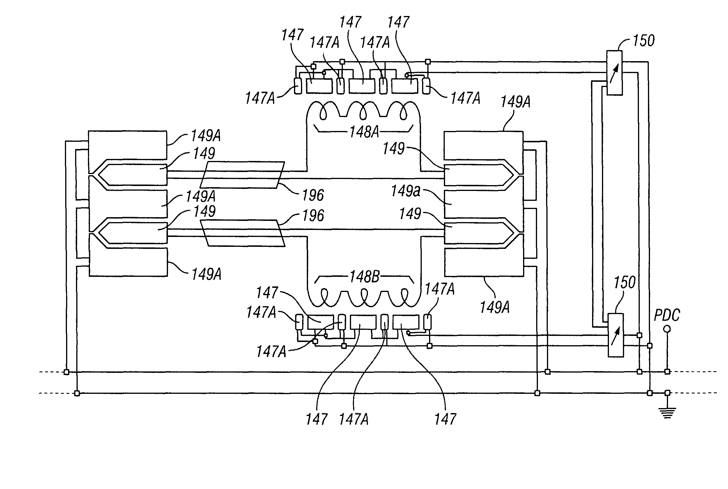
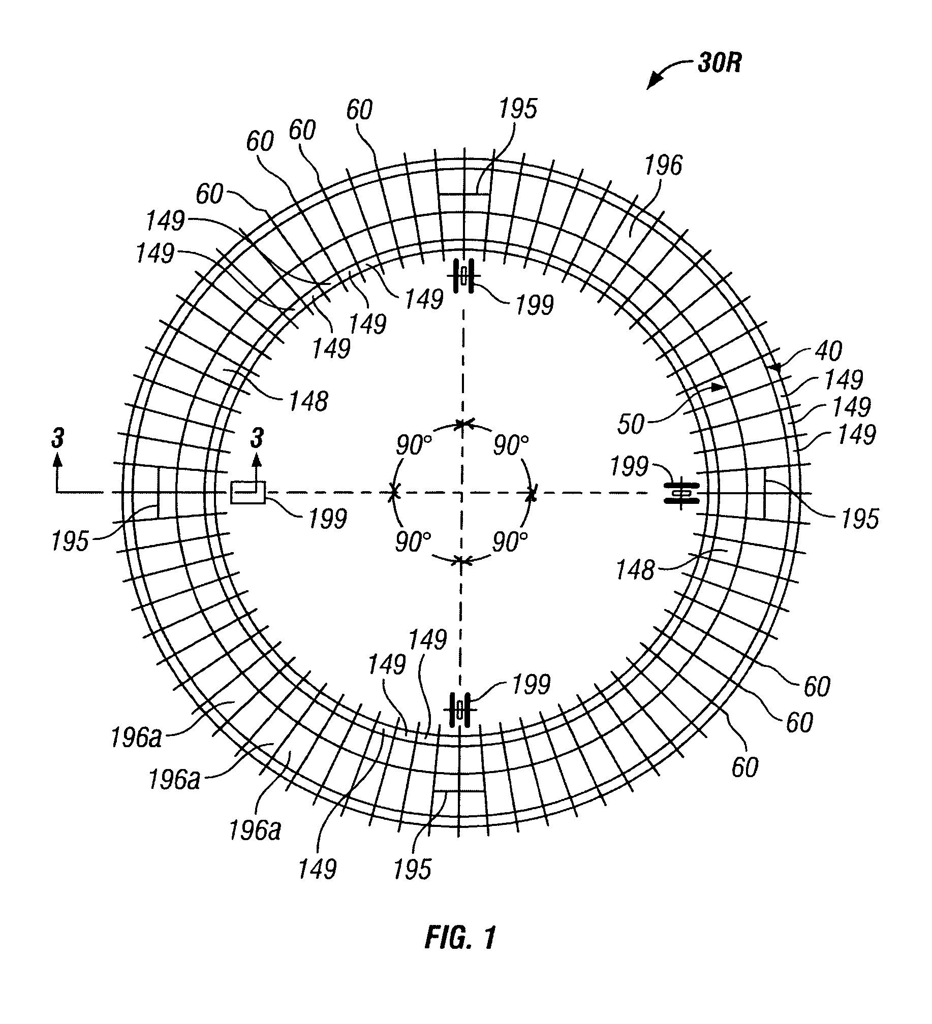
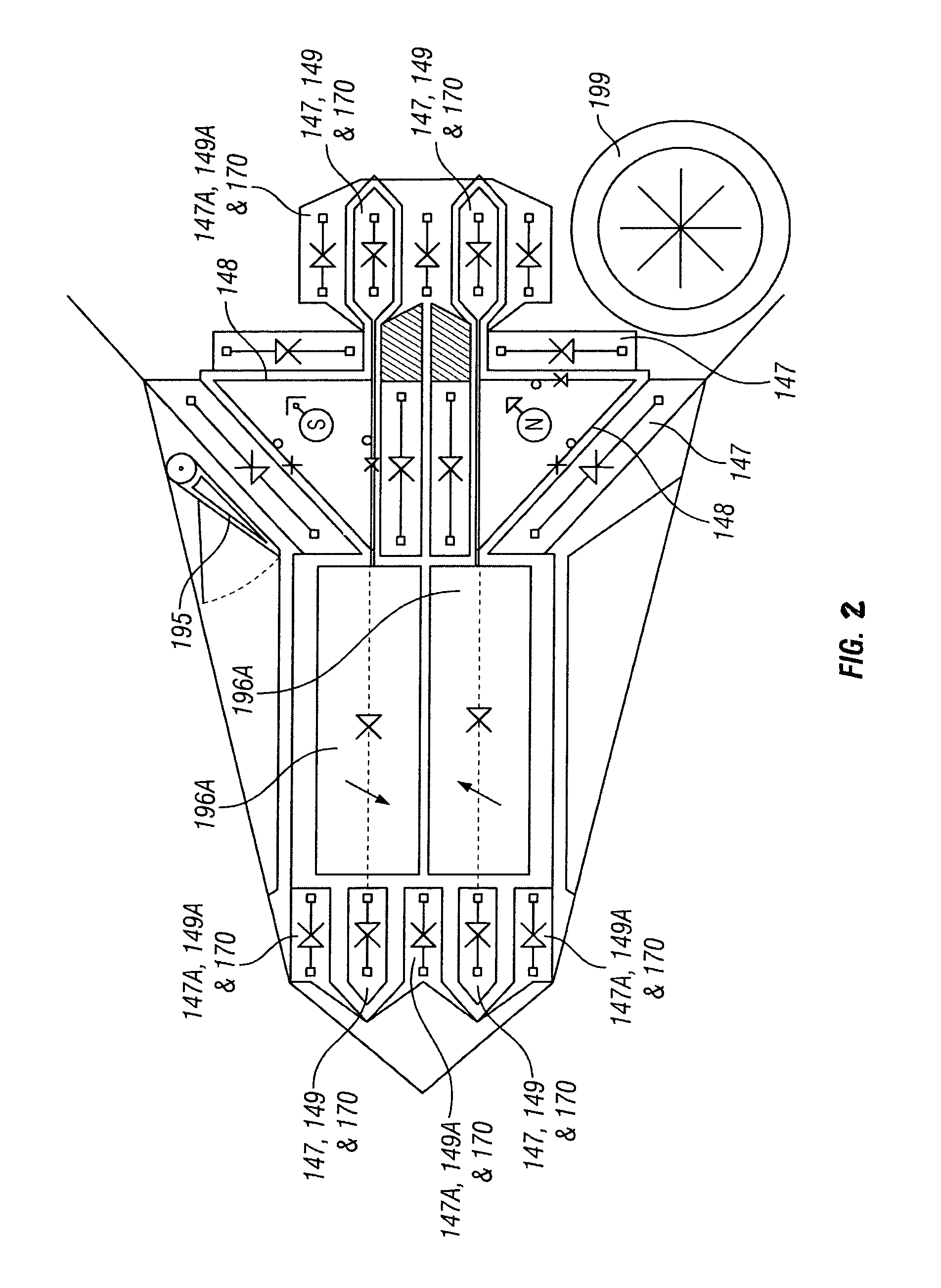
[0025]The present invention apparatus is described now as a flying craft 10 which has an aerodynamic fuselage structure preferably disc shaped. Referring now to FIGS. 2 and 6 which shows, in section, one radial portion of a plurality of coaxial electric motors 20 which are mounted concentrically, and preferably centered within the disc shaped structure of flying craft 10. Motors 20 are toroidal in config...


PUM


Abstract

A flying craft has an aerodynamic aircraft fuselage structure preferably disc shaped. A pair of coaxial electrokinetic motor-generators are mounted concentrically, and preferably centered within the disc shaped structure of the craft. Each of the motors is toroidal in configuration, providing a ring-shaped stator and rotor portions. The rotor portions of the motors drive counter rotating fans which are electro-magnetically levitated. The structure is open to the fans so that air may be drawn into the structure and expelled downward providing vertical lift to the aircraft. By use of auxiliary air braking flaps and electrokinetic thrusters, the craft may be tilted so as to develop a desired horizontal thrust. By impulse breaking one of the fans through tracking solenoids at different points around the stator, the aircraft may be made to rotate about its own vertical axis for changing direction. By a series of sudden braking of the motors the craft may be made to move by inertial reaction.

Description

CROSS-REFERENCE TO RELATED APPLICATIONS[0001]This is a continuation-in-part application of U.S. patent application Ser. No. 11 / 210,035, filed on Aug. 22, 2005 now abandoned which is herewith and which is incorporated herein by reference.STATEMENT REGARDING FEDERALLY SPONSORED RESEARCH OR DEVELOPMENT[0002]Not applicable.THE NAMES OF THE PARTIES TO A JOINT RESEARCH AGREEMENT[0003]Not applicable.INCORPORATION-BY-REFERENCE OF MATERIAL SUBMITTED ON A COMPACT DISC[0004]Not applicable.REFERENCE TO A “MICROFICHE APPENDIX”[0005]Not applicable.BACKGROUND OF THE INVENTIONField of the Present Disclosure[0006]This disclosure relates generally to electric motor-generators and more particularly to a DC rotating electromagnetic machine operating by induction as a flying craft.Description of Related Art including information disclosed under 37 CFR 1.97 and 1.98[0007]Tu et al, US 2004 / 0135452, discloses a flat rotary electric generator that includes at least one toroidal coil structure for cutting ma...

Claims


Application Information

Patent Timeline
Patent Type & Authority Patents(United States)
IPC IPC(8): B64C27/20B64C39/00
CPCB64C39/001B64C29/0025
Inventor BOJIUC, DUMITRU
Owner CLEARWATER HLDG
Why Eureka
Try Eureka