Delivery system having a rapid pusher assembly for self-expanding stent, and stent exchange configuration

a technology of stent pusher and pusher assembly, which is applied in the direction of stents, blood vessels, medical science, etc., can solve the problems of affecting the visibility of stenosis, slow resulting distal advancement of the same sheath, etc., and achieves the effect of reducing the risk of interfering with the stenosis, reducing the risk of stenosis, and thin and flexibl

Active Publication Date: 2011-12-13
ANGIOMED GMBH & CO MEDIZINTECHNIK KG
View PDF286 Cites 64 Cited by
  • Summary
  • Abstract
  • Description
  • Claims
  • Application Information

AI Technical Summary

Benefits of technology

[0028]According to another aspect of the present invention, there is provided a stent delivery system having a rapid exchange configuration for a self-expanding stent which provides improved visualisation through an increased volume flow in each pulse. The volume flow in each pulse is increased in the present invention due to a simplified and reduced internal structure of the delivery system.
[0038]In yet another aspect of the invention, the modular construction of the delivery device results in fewer steps during manufacturing and assembly of the stent delivery system. The device may be modularized by using a transfer shaft connecting the rod or inner catheter with the pusher element. This can be set to any desired length, to accommodate stents of different length in a delivery system which features standard length catheter components such as the sheath, rod or inner catheter and pusher tube. It may be convenient to use a welded joint to fasten one or both of the two ends of the transfer shaft to the pusher element and rod, respectively.

Problems solved by technology

The visibility of the stenosis is adversely affected when the lumen, through which radiopaque contrast fluid is injected, is too small to deliver a strong pulse of contrast fluid.
For example, a fast squeeze of the trigger of a deployment system at the proximal end of the sheath will likely result in a somewhat slower resulting proximal advancement of the distal end of the same sheath.

Method used


Image

  • Delivery system having a rapid pusher assembly for self-expanding stent, and stent exchange configuration
  • Delivery system having a rapid pusher assembly for self-expanding stent, and stent exchange configuration
  • Delivery system having a rapid pusher assembly for self-expanding stent, and stent exchange configuration

Examples


Embodiment Construction

[0049]The following description of the preferred embodiments of the present invention is merely illustrative in nature, and as such does not limit in any way the present invention, its application, or uses.

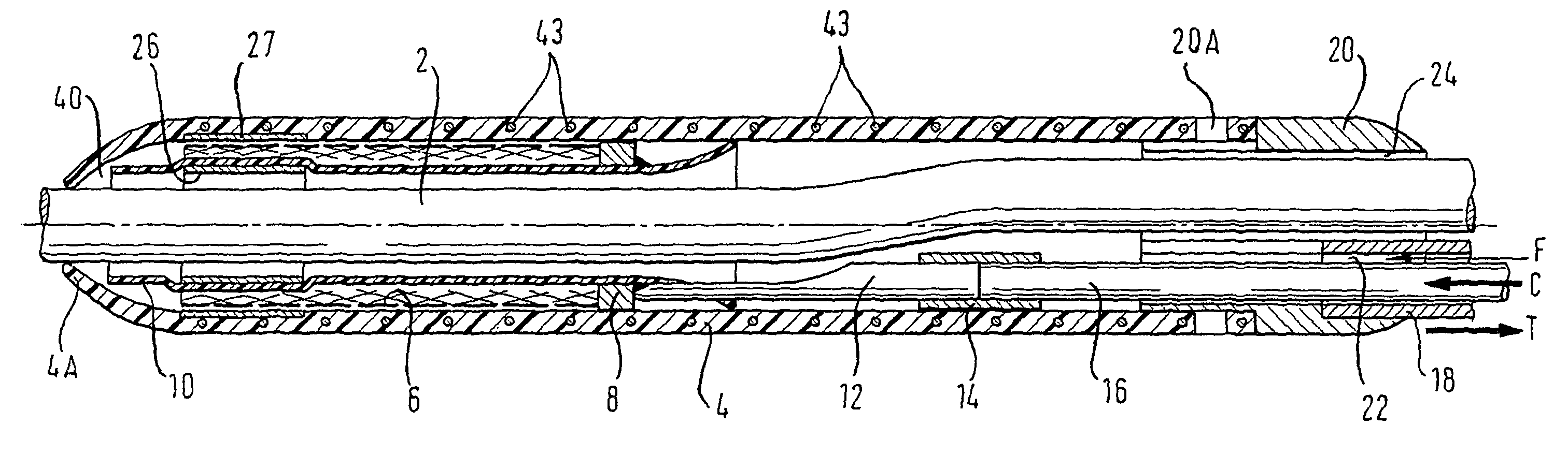
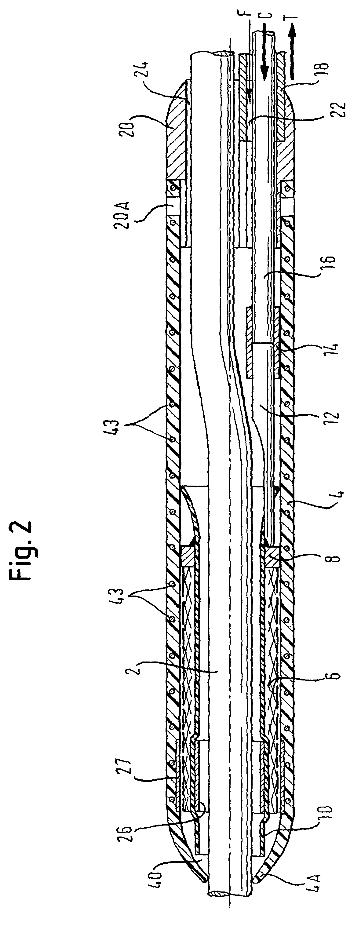
[0050]FIG. 2 shows a cross-section of the distal portion of a delivery system having a rapid-exchange configuration in accordance with a preferred embodiment of the present invention.

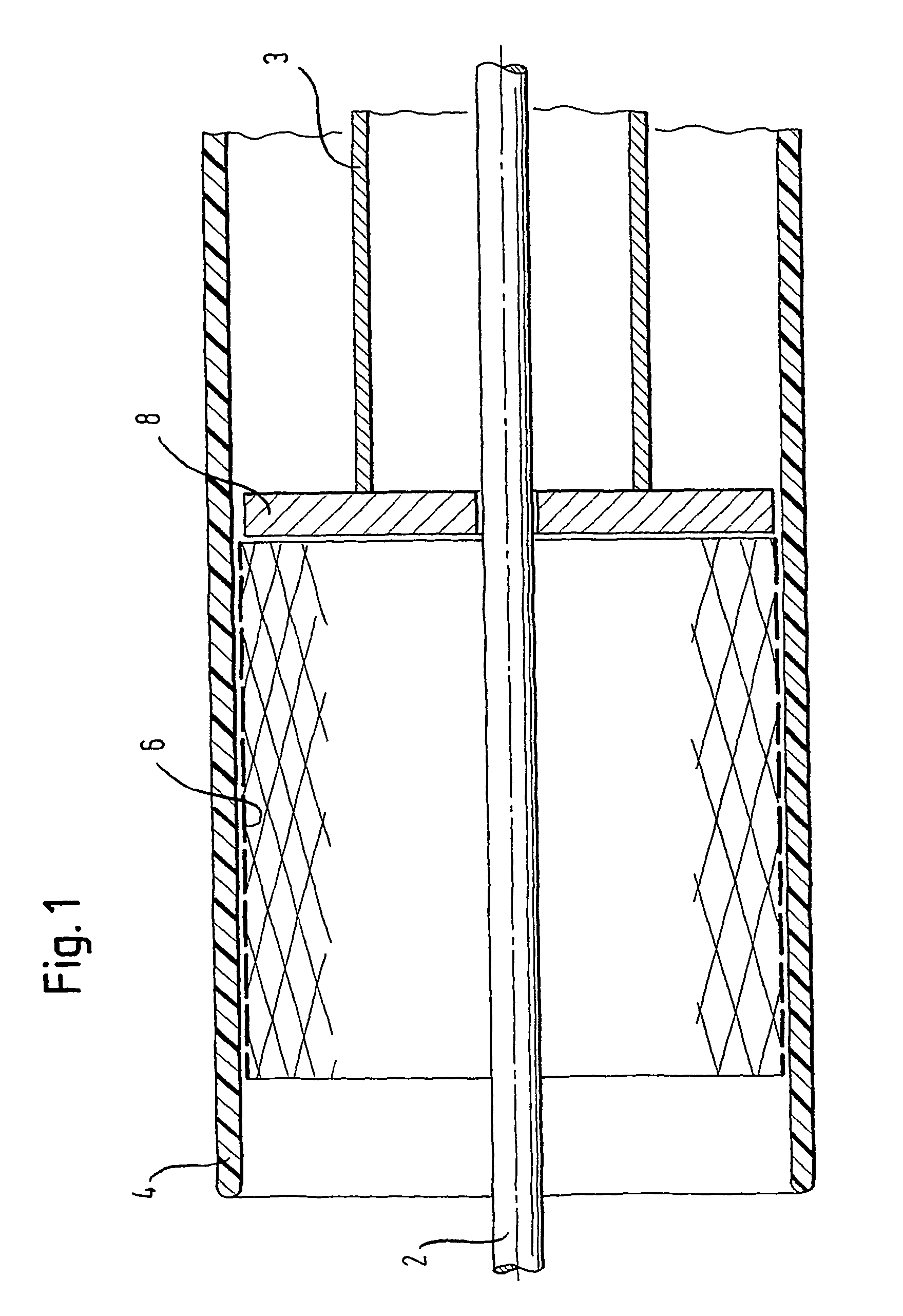
[0051]In FIG. 2, a guidewire 2 extends beyond the distal end of the distal portion of the delivery system along which the stent delivery system is advanced to the site of the stenosis inside the patient's body. The stent 6 is held in a radially compressed state by means of an outer sheath 4 the distal end of which constitutes the distal end of the stent delivery system. The distal tip 4A of the outer sheath 4, as shown in FIG. 2, is tapered in order to facilitate advance of the stent delivery system along a bodily lumen. Furthermore, the outer sheath 4 comprises a radiopaque marker 27 the position of ...


PUM


Abstract

A pusher assembly for a delivery system for a self-expanding stent (6) which is delivered by proximal withdrawal of a sheath (4) radially surrounding the stent has a stent pusher element (8) which defines a lumen for a guidewire (2), a pusher strand (16) that extends to the proximal end of the delivery system and bears an end-wise compressive stress during release of the stent. A transfer shaft (12) links the distal end of the pusher strand (16) to the pusher element (8) and lies side-by-side with the guidewire (2). In a rapid exchange version, an adapter (20) provides two lumens side-by-side, one (22) carrying the pusher strand (16) and the other (14) defining a proximal guidewire part. To the adapter is mounted the proximal end of the stent sheath (4). The system allows modular (14) construction, a tapered tip (4A) on the sheath, and an uncluttered internal configuration which facilitates passage of pulses (F) of liquids from the proximal to the distal end of the system.

Description

TECHNICAL FIELD[0001]This invention relates to a stent pusher assembly, and to a delivery system having a rapid-exchange configuration for deploying a self-expanding stent at a stenting site within a human or animal body.BACKGROUND AND CONTENT OF THE INVENTION[0002]EP-A-1 095 634 (EP 634) discloses all features of the preamble of independent claims 1 and 11. EP 634 discloses a system in which the soft atraumatic distal tip of the system is at the leading end of the inner catheter. The outer sheath of the delivery system has a distal end which stops proximally short of the atraumatic tip.[0003]Stents to be deployed at a stenting site within a human or animal body expand radially in the course of delivery, from a radially compact delivery disposition to a radially larger deployed disposition. In self-expanding stents made of stainless steel, the deformation of the stent is below the elastic limit, the stent until its deployment being radially confined and under elastic stress and typi...

Claims


Application Information

Patent Timeline
Patent Type & Authority Patents(United States)
IPC IPC(8): A61F2/06A61F2/00A61F2/95A61F2/966
CPCA61F2/95A61F2/966A61F2250/0098
Inventor DORN, JURGEN
Owner ANGIOMED GMBH & CO MEDIZINTECHNIK KG
Why Eureka
Try Eureka