Acoustic/pressure wave-driven separation device

a separation device and pressure wave technology, applied in the direction of mechanical vibration separation, membrane separation, separation process, etc., can solve the problems of the most difficult or costly mixture to separate, and the combination of two liquids having similar boiling points can be especially expensive to separate by traditional means,

Inactive Publication Date: 2011-12-13
THE BOARD OF RGT UNIV OF OKLAHOMA
View PDF17 Cites 47 Cited by
  • Summary
  • Abstract
  • Description
  • Claims
  • Application Information

AI Technical Summary

Problems solved by technology

This applies especially to mixtures containing components having similar properties, and / or mixtures having a solid dissolved or otherwise dispersed within a liquid on a small scale that are often the most difficult or costly mixtures to separate.
For example, a mixture of two liquids having similar boiling points can be especially expensive to separate by traditional means, such as distillation.
Additionally, mixtures having a solid dissolved or otherwise dispersed in a liquid on a small scale can be especially difficult to separate by traditional means, such as screening and or filtration.
The demand for efficient and effective separation or desalinization of saltwater is ever increasing, especially as the earth's population increases and traditional freshwater sources become contaminated with pollutants.
Additionally, the oscillations in pressure, and thereby temperature and volume, are limited by the power of the acoustic waves supplied, and thus higher capacity for thermal transport against the gradient may, in some cases, be more easily achieved by increasing the surface area of the plate or plates available for the transfer and transport of thermal energy.

Method used


Image

  • Acoustic/pressure wave-driven separation device
  • Acoustic/pressure wave-driven separation device
  • Acoustic/pressure wave-driven separation device

Examples


second embodiment

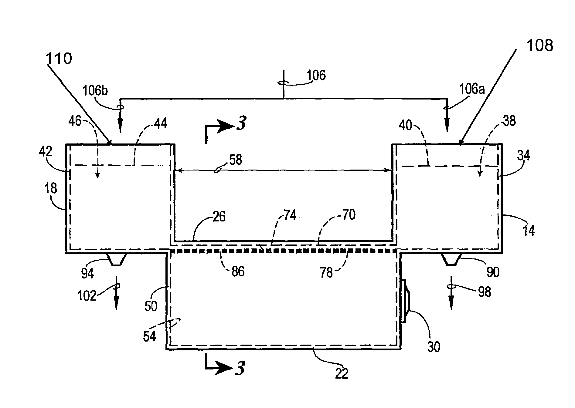
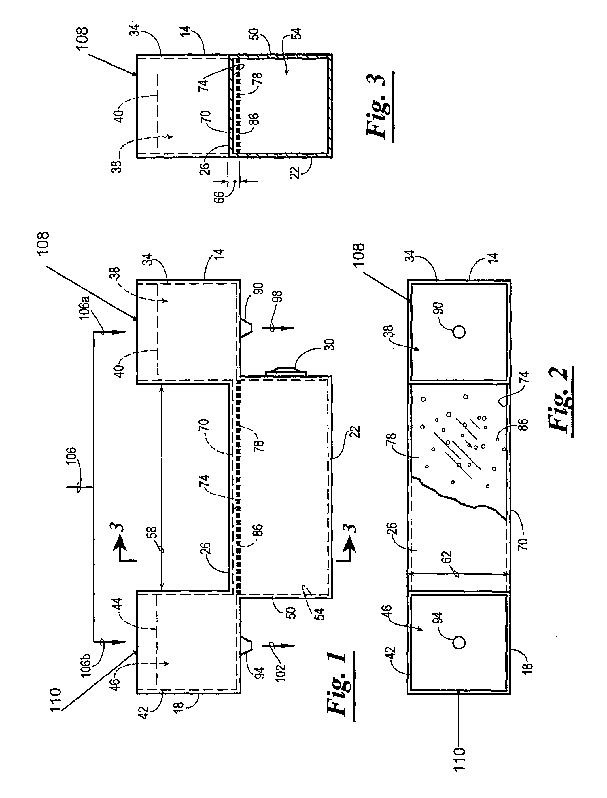
[0093]Referring again to the drawings, shown in FIG. 6 is a perspective-view diagram of an acoustically / pressure wave-driven separation device 10a as constructed in accordance with the present invention and referred to therein by the general reference numeral 10a. The device 10a is similar in many respects, in both form and function, to the device 10 of FIGS. 1-5G. Specifically, the device 10a is preferably provided with a lean reservoir 14a, a rich reservoir 18a, a pump reservoir 22a, a bridge structure 26a, and an acoustic / pressure wave source 30a. The lean and rich reservoirs 14a and 18a, respectively, are filled during operation with crude mixture streams 106a and 106b, respectively. Similarly, the lean and rich reservoirs 14a and 14b, respectively, are drained by lean and rich product streams 98a and 102a, respectively, via product outlets 90a and 94a, respectively.

[0094]The primary difference between the device 10a and the device 10 (FIGS. 1-3), is that the bridge structure 26...

third embodiment

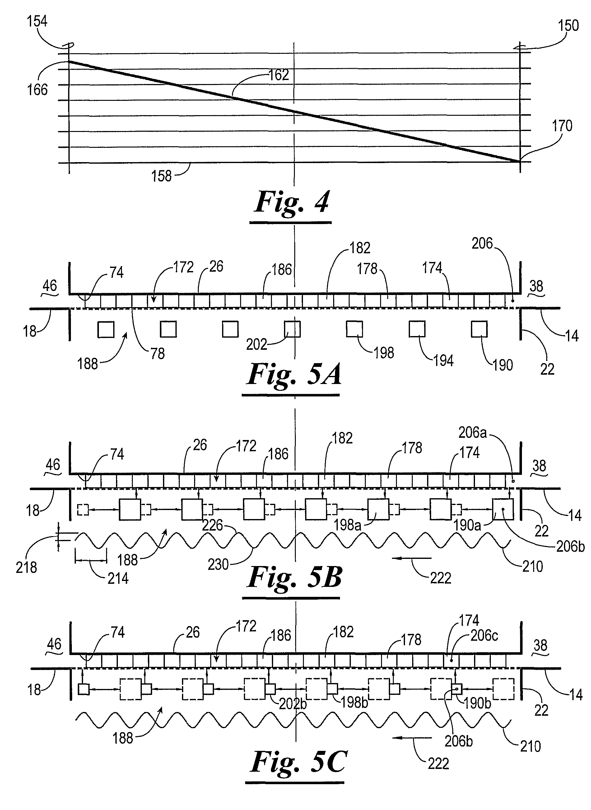
[0096]Referring now to FIG. 7, shown therein is a side-view diagram of an acoustic / pressure wave-driven separation device constructed in accordance with the present invention and referenced therein by general reference numeral 10b. The device 10b is adapted with three concentration reservoirs 250a, 250b, and 250c, such that the device 10b is capable of separating a crude mixture into three components and / or component mixtures or sub-mixtures. With the exception of several changes in form and the addition of an additional separation function, the device 10b is similar in many respects, in both form and function, to the device 10 of FIGS. 1-3 and the device 10a of FIG. 6. The device 10, 10a and 10b can have one or more pressure wave source(s) and one or more pump reservoir.

[0097]For example, the device 10b is provided with a plurality of concentration reservoirs, e.g. 250a, 250b, and 250c (and optionally more than three), a pump reservoir 22b, a bridge structure 26b, and an acoustic / p...

fourth embodiment

[0102]Referring now, to FIG. 8, a side view diagram of an acoustic / pressure wave-driven device, for separating a mixture into five components, constructed in accordance with the present invention and designated by the general reference numeral 10c. Similar to the device 10b of FIG. 7, the device 10c is provided with a plurality of concentration tanks 260a, 260b, 260c, 260d, and 260e, each having an inner space 264a, 264b, 264c, 264d, and 264e, respectively. The device 10c also preferably comprises a bridge structure 26c defining a gradient channel 74c extending across and in fluid communication with each of the spaces 264a, 264b, 264c, 264d, 264e so as to permit the various target components A, B, C, D, E to maintain respective concentration gradients within the gradient channel 74c. Additionally, the device 10c is provided with at least one acoustic / pressure wave source 30c similar to the other acoustic / pressure wave sources 30-30b described elsewhere herein.

[0103]The primary diffe...


PUM

PropertyMeasurementUnit
concentrationaaaaaaaaaa
volumeaaaaaaaaaa
lengthaaaaaaaaaa

Abstract

An acoustic / pressure wave-driven device for separating a first component from a mixture of the first component and a second fluid component. The device comprises a rich reservoir, a lean reservoir, a pump reservoir, a bridge structure, and an acoustic / pressure wave source. The rich reservoir is for containing a fluid mixture having an elevated concentration of the first component. The lean reservoir is for containing a fluid mixture having a lesser concentration of the first component that is leaner than the concentration of the first component in fluid mixture of the rich reservoir. The pump reservoir contains a fluid mixture of the first component and the second fluid component. The bridge structure has a sidewall defining a gradient channel in fluid communication with the rich reservoir and the lean reservoir and a length extending there between. The gradient channel is for containing a fluid having a concentration gradient of the first component along its length. A diffusion portion of the sidewall disposed between the gradient channel and the pump reservoir is adapted to permit diffusion of at least the first component between the gradient channel and the pump reservoir while preventing fluid flow there between. The acoustic / pressure wave source provides acoustic waves into the pump reservoir to cause pressure oscillations in the fluid mixture therein adjacent to the diffusion portion to move molecules of the target component against the concentration gradient from the lean reservoir into the rich reservoir.

Description

CROSS-REFERENCE TO RELATED APPLICATIONS[0001]The present patent application claims benefit of provisional patent application No. 60 / 842,332, filed on Sep. 5, 2006, the entire content of which is hereby incorporated herein by referenceSTATEMENT REGARDING FEDERALLY-FUNDED RESEARCH AND DEVELOPMENT[0002]Not applicable.THE NAMES OF THE PARTIES TO A JOINT RESEARCH AGREEMENT[0003]Not applicable.BACKGROUND OF THE INVENTION[0004]1. Field of the Invention[0005]The present invention relates generally to separating components of mixtures. More specifically, but not by way of limitation, the present invention relates to pressure-driven devices for moving molecules of at least one component against a concentration gradient to separate the at least one component from a mixture.[0006]2. Discussion of Related Art[0007]Separating mixtures efficiently and cost-effectively has long been an object of the prior art. More specifically, it is often desirable to separate one or more components out of a mixt...

Claims


Application Information

Patent Timeline
Patent Type & Authority Patents(United States)
IPC IPC(8): C02F1/32C10G9/18C10G31/06
CPCB01D61/00C02F1/36B01D2315/04C02F2101/32C02F2101/34C02F2103/08Y02A20/144
Inventor BAGAJEWICZ, MIGUEL J.
Owner THE BOARD OF RGT UNIV OF OKLAHOMA
Why Eureka
Try Eureka