Semiconductor device with trench of various widths

a technology of semiconductor devices and trenches, applied in the direction of semiconductor devices, electrical equipment, transistors, etc., can solve the problems of frequent leakage current phenomenon, affecting the etc., and achieve the effect of improving reliability and performance of the devi

Active Publication Date: 2011-12-13
MARLIN SEMICON LTD
View PDF15 Cites 16 Cited by
  • Summary
  • Abstract
  • Description
  • Claims
  • Application Information

AI Technical Summary

Benefits of technology

[0007]Accordingly, the invention provides a method of fabricating a semiconductor device to carry out an ion implantation process before dummy patterns are formed, so as to enhance the reliability and performance of the device.
[0028]In light of the foregoing, in the method of fabricating the semiconductor device of the invention, the ion implantation process is performed after the polysilicon layer is formed. Thus, when removing a portion of the polysilicon layer, different etching rates at different depth locations of the doped polysilicon layer are utilized to form the dummy patterns having the width of the neck narrower than the width of the top. Hence, when removing the dummy patterns and filling the metal layer, not only are the dummy patterns removed rapidly, but the effect of metal gap fill is also improved, such that voids do not form easily, thereby greatly enhancing the reliability and performance of the device.
[0029]The gate structure of the semiconductor device in the invention is disposed in the trench having a wide opening in the top portion. Therefore, the metal layer of the gate structure does not include voids and can have superior device performance.

Problems solved by technology

However, the leakage current phenomenon frequently occurs when reducing the thickness of the gate dielectric layers adopting silicon oxide.
Hence, when the opening is filled with the metal layer by a sputtering process, the effect of metal gap fill is poor, so that problems such as overhang and the like usually occur to cause the formation of voids in the metal layer, thereby affecting the reliability and performance of the device.

Method used


Image

  • Semiconductor device with trench of various widths
  • Semiconductor device with trench of various widths
  • Semiconductor device with trench of various widths

Examples


Embodiment Construction

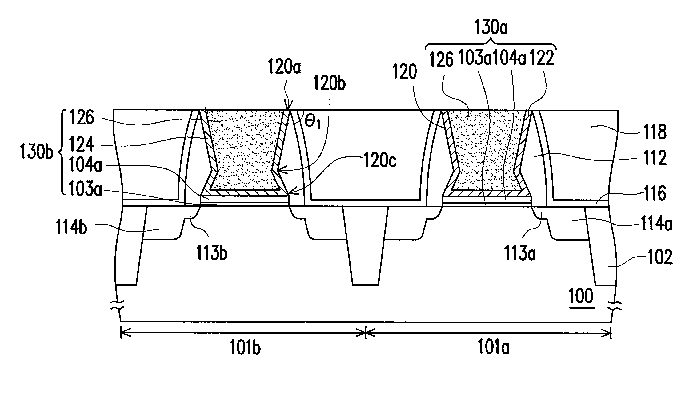
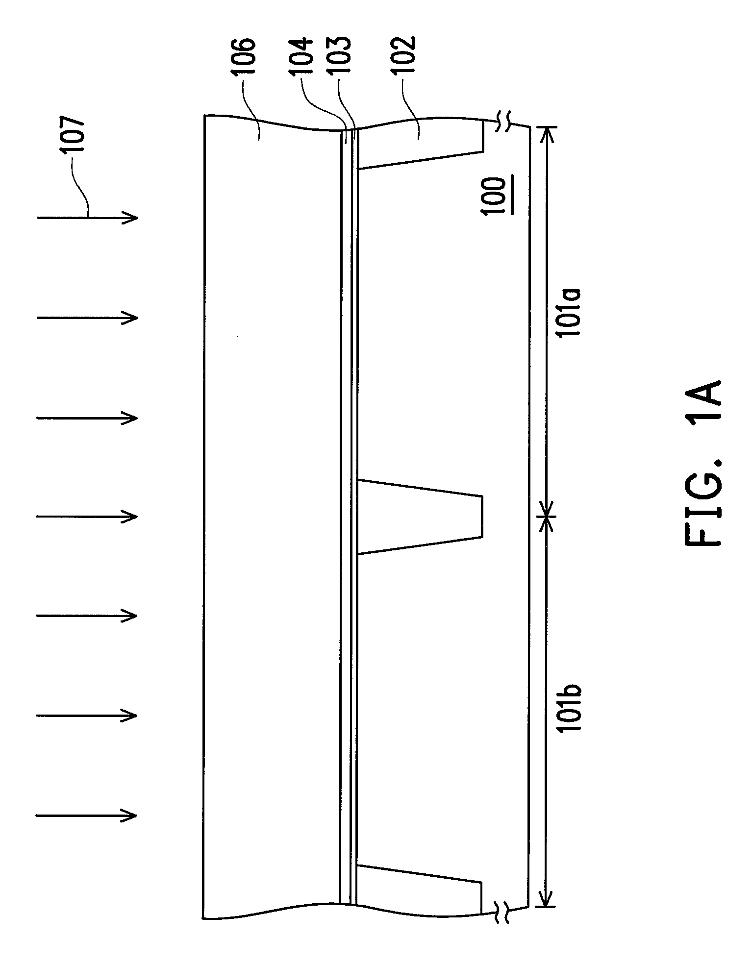
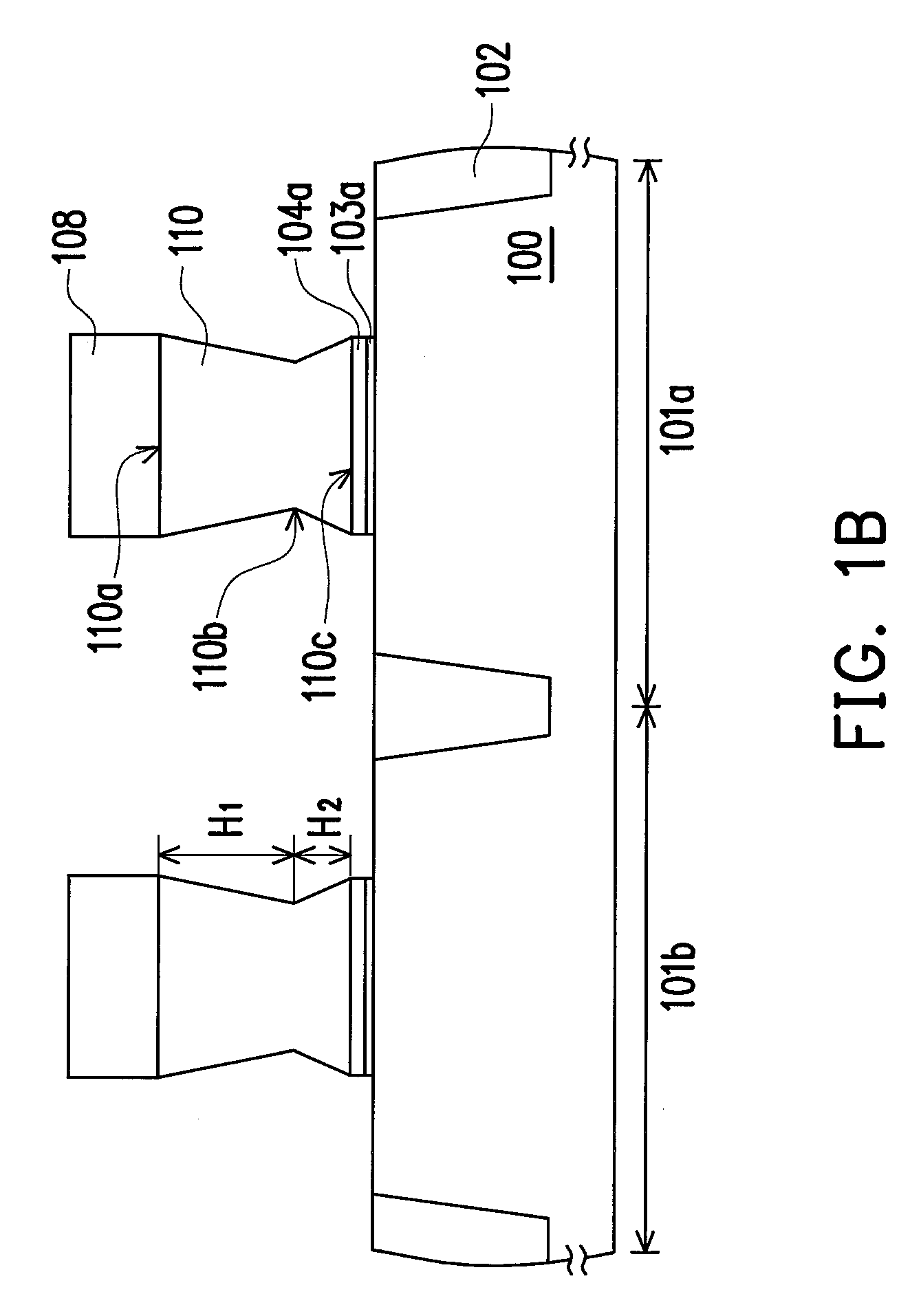
[0035]FIGS. 1A through 1E are cross-sectional views schematically illustrating a process for fabricating a semiconductor device according to an embodiment of the invention. It should be noted that the method of fabricating the semiconductor device described in the following adopts a gate last process to form a complementary metal oxide semiconductor (CMOS) device for illustration. People skilled in the art should be able to embody the invention based on the illustration, whereas the scope of the invention is not limited thereto. The formation of a single metal oxide semiconductor (MOS) device may also be implemented. Moreover, the disposition locations, the manners and the sequence of formation of other components such as metal gate structures, doped regions, spacers, stop layers, and the like are all fabricated with techniques known to people skilled in the art based on conventional arts, and are not limited to the descriptions illustrated in the following embodiments.

[0036]Referri...


PUM


Abstract

A semiconductor device and a method for fabricating the same are described. A polysilicon layer is formed on a substrate. The polysilicon layer is doped with an N-type dopant. A portion of the polysilicon layer is then removed to form a plurality of dummy patterns. Each dummy pattern has a top, a bottom, and a neck arranged between the top and the bottom, where the width of the neck is narrower than that of the top. A dielectric layer is formed on the substrate to cover the substrate disposed between adjacent dummy patterns, and the top of each dummy pattern is exposed. Thereafter, the dummy patterns are removed to form a plurality of trenches in the dielectric layer. A plurality of gate structures is formed in the trenches, respectively.

Description

BACKGROUND OF THE INVENTION[0001]1. Field of the Invention[0002]The invention relates to a semiconductor device and a method of fabricating the same. More particularly, the invention relates to a void-free semiconductor device and a method of fabricating the same.[0003]2. Description of Related Art[0004]With the continual miniaturization of semiconductor devices, dimensions of gate structures are also gradually reduced. Therefore, the thickness of gate dielectric layers also needs to be reduced to prevent the performance of the devices from being affected. Generally, the material of the gate dielectric layers usually includes silicon oxide. However, the leakage current phenomenon frequently occurs when reducing the thickness of the gate dielectric layers adopting silicon oxide. In order to reduce the occurrence of leakage current, a conventional method is to replace silicon oxide with high dielectric constant (high-k) material for the gate dielectric layers. When applying high diele...

Claims


Application Information

Patent Timeline
Patent Type & Authority Patents(United States)
IPC IPC(8): H01L29/76H01L27/108H01L31/119H01L31/113H01L31/062H01L29/94
CPCH01L21/28088H01L21/28114H01L21/823807H01L21/82385H01L21/823864H01L29/42376H01L29/4966H01L29/66545H01L29/7833H01L29/7843
Inventor LIN, CHUN-HSIEN
Owner MARLIN SEMICON LTD
Why Eureka
Try Eureka