Electro-optical device and electronic apparatus

a technology of electro-optical devices and electronic devices, applied in the direction of instruments, electric digital data processing, computing, etc., can solve the problems of low visibility of the display of electro-optical devices, reduced ambient brightness around electro-optical devices, and difficulty in increasing display visibility

Inactive Publication Date: 2011-12-13
JAPAN DISPLAY WEST
View PDF17 Cites 5 Cited by
  • Summary
  • Abstract
  • Description
  • Claims
  • Application Information

AI Technical Summary

Benefits of technology

[0019]Although ambient light has a substantially constant intensity, for example, when the ambient light is shielded by an operation performed on the display unit or light from a light source is reflected, the light intensities detected by the optical sensors may have unique values. The controller that selectively performs recognition of the operation position on the display unit or measurement of the ambient light intensity on the basis of the light intensities detected by the plurality of optical sensors allows selective provision of a period during which the operation position on the display unit is recognized and a period during which the ambient light intensity is measured. Therefore, even if a unique light intensity is detected by an operation performed on the display unit, the ambient light intensity can be determined without taking the unique light intensity into consideration, and measurement accuracy of the ambient light intensity can be increased.
[0023]Since the light source and the light source controller are provided, the intensity of light supplied from the light source can be controlled according to the ambient brightness around the electro-optical device. The visibility of the display of the electro-optical device can therefore be increased regardless of the ambient brightness around the electro-optical device.
[0025]Accordingly, the ambient light intensity is measured according to a light intensity that is within a predetermined range among the light intensities detected by the plurality of optical sensors. Therefore, even if a unique light intensity is detected by an operation performed on the display unit, the ambient light intensity can be determined without taking the unique light intensity into consideration, and measurement accuracy of the ambient light intensity can be increased.
[0027]Accordingly, the ambient light intensity is measured according to a light intensity detected by an optical sensor that is located in an area other than the predetermined area among the plurality of optical sensors. Therefore, even if a unique light intensity is detected by whatever operation performed within the predetermined area, the ambient light intensity can be measured without taking the unique light intensity into consideration, and measurement accuracy of the ambient light intensity can further be increased.

Problems solved by technology

That is, as the ambient brightness around the electro-optical devices increases, the contrast between the brightness of the display areas of the electro-optical devices and the ambient brightness around the electro-optical devices is reduced, resulting in low visibility of the display of the electro-optical devices.
However, the electro-optical device disclosed in JP-A-11-119898 is not configured to measure the ambient light intensity and it is therefore difficult to increase the visibility of the display.

Method used


Image

  • Electro-optical device and electronic apparatus
  • Electro-optical device and electronic apparatus
  • Electro-optical device and electronic apparatus

Examples


first embodiment

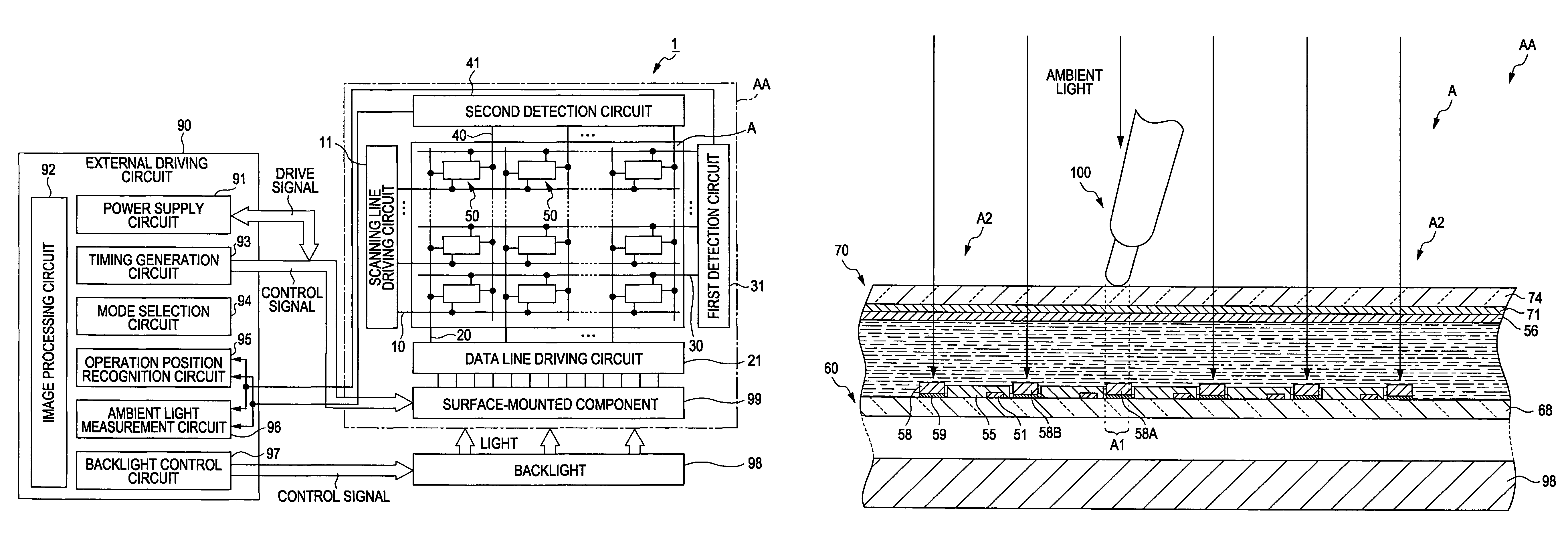
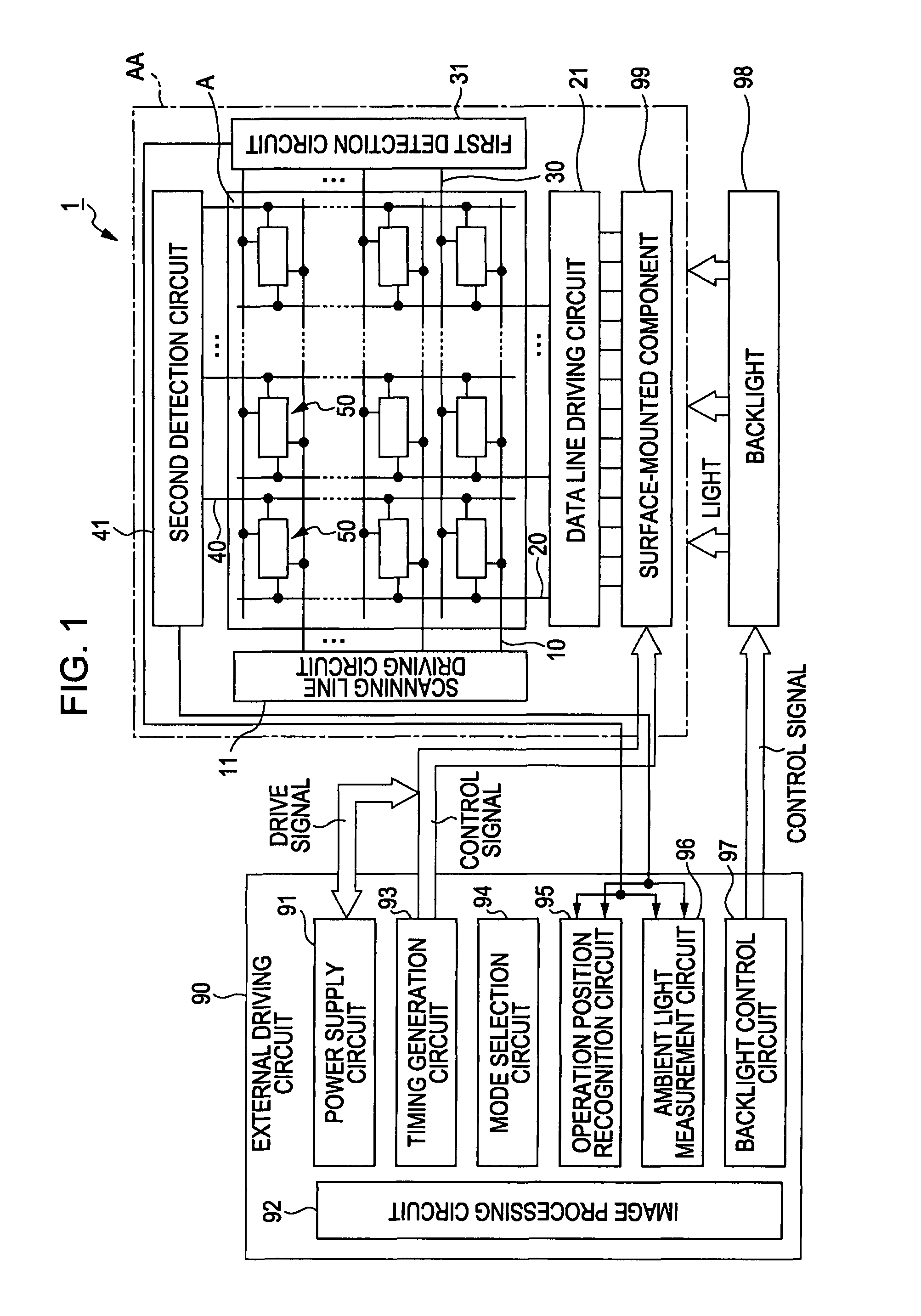
[0045]FIG. 1 is a block diagram showing the structure of an electro-optical device 1 according to a first embodiment of the invention.

[0046]The electro-optical device 1 includes a liquid crystal panel AA, an external driving circuit 90 that drives the liquid crystal panel AA, and a backlight 98 serving as a light source that irradiates the liquid crystal panel AA with light. The electro-optical device 1 performs transmission type display using the light from the backlight 98, and acts as a touch panel to perform display in accordance with an operation of an input pen 100 (see FIG. 7) on a display area A, described below.

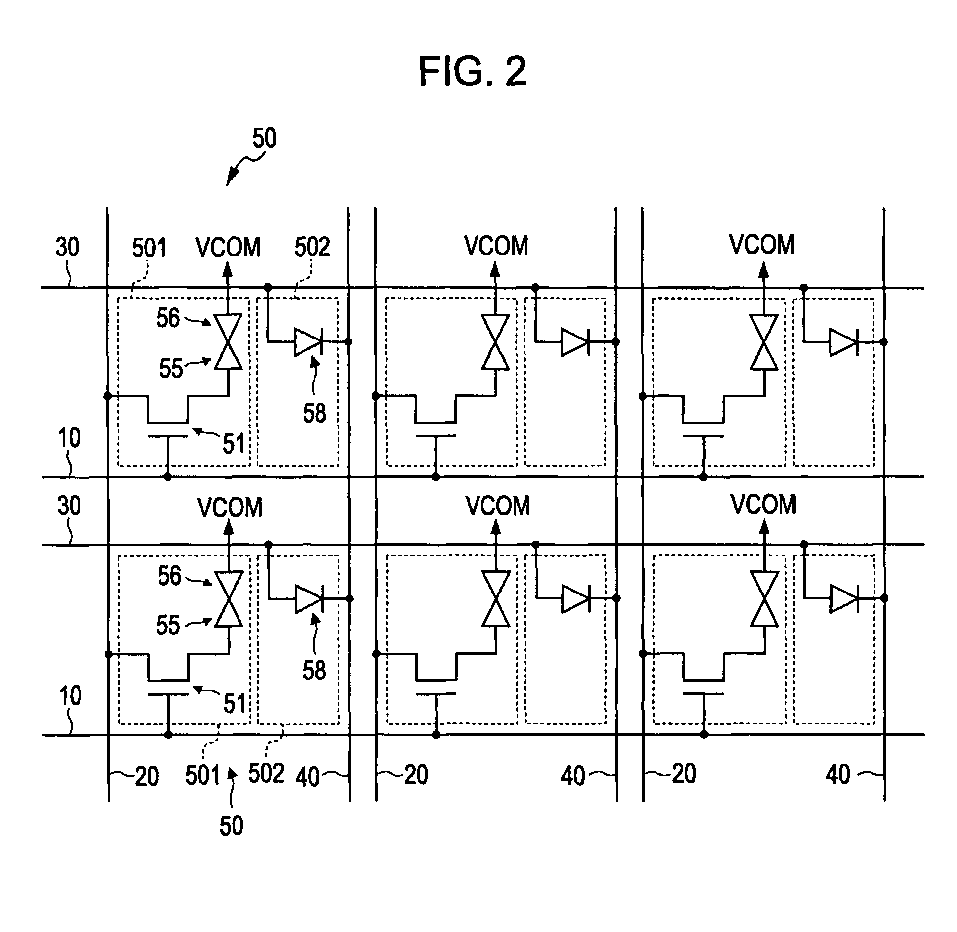
[0047]The liquid crystal panel AA includes a plurality of scanning lines 10, a plurality of data lines 20 crossing the scanning lines 10 and disposed at predetermined intervals, and pixels 50 disposed at intersections of the scanning lines 10 and the data lines 20. In the liquid crystal panel AA, the pixels 50 are arranged to form a display area A. A scanning line dr...

second embodiment

[0107]FIG. 11 is a block diagram showing the structure of an electro-optical device 1A according to a second embodiment of the invention.

[0108]The second embodiment is different from the first embodiment in that an external driving circuit 90A includes an available area selection circuit 94A, an operation position recognition circuit 95A, and an ambient light measurement circuit 96A in place of the mode selection circuit 94, the operation position recognition circuit 95, and the ambient light measurement circuit 96. Other structural features are similar to those of the first embodiment.

[0109]FIG. 12 is a diagram showing a display area A of the electro-optical device 1A.

[0110]The available area selection circuit 94A selects from the display area A an available area A5 that can be operated by the input pen 100, and outputs position information of photodiodes 58E that are located in the available area A5 to the operation position recognition circuit 95A. The available area selection ci...

application examples

[0129]An electronic apparatus including the electro-optical device 1 according to the embodiment described above will be described.

[0130]FIG. 13 is a perspective view showing the structure of a mobile phone 3000 using the electro-optical device 1. The mobile phone 3000 includes a plurality of operation buttons 3001 and scroll buttons 3002, and the electro-optical device 1. The scroll buttons 3002 are operated to scroll a screen displayed on the electro-optical device 1.

[0131]Electronic apparatuses using the electro-optical device 1 include, not only the mobile phone 3000 shown in FIG. 13, but also various electronic apparatuses such as personal computers, portable information terminals, digital still cameras, liquid crystal televisions, view-finder-type or monitor-direct-view-type video tape recorders, car navigation systems, pagers, electronic notebooks, electronic calculators, word processors, workstations, videophones, point-of-sale (POS) terminals, and apparatuses equipped with ...


PUM


Abstract

An electro-optical device includes a display unit having a plurality of pixels, and the display unit is divided into a plurality of areas. The electro-optical device also includes a plurality of optical sensors that are provided for the plurality of areas, each of the optical sensors being configured to detect a light intensity, and a controller that selectively performs recognition of an operation position on the display unit or measurement of an ambient light intensity on the basis of the light intensities detected by the plurality of optical sensors.

Description

BACKGROUND[0001]1. Technical Field[0002]The present invention relates to electro-optical devices and electronic apparatuses.[0003]2. Related Art[0004]Electro-optical devices for liquid crystal display apparatuses have been known. The electro-optical devices include, for example, a liquid crystal panel, and a backlight for supplying light to the liquid crystal panel.[0005]The liquid crystal panel includes an element substrate having thin film transistors (TFTs) serving as switching elements, described below, arranged in a matrix, a counter substrate facing the element substrate, and a liquid crystal as an electro-optical material disposed between the element substrate and the counter substrate.[0006]The element substrate includes a plurality of scanning lines disposed at predetermined intervals, and a plurality of data lines crossing those scanning lines and disposed at predetermined intervals.[0007]Pixels are disposed at intersections of the scanning lines and the data lines. Each o...

Claims


Application Information

Patent Timeline
Patent Type & Authority Patents(United States)
IPC IPC(8): G09G3/36
CPCG06F3/0412G06F3/042G09G3/3406G09G2300/0809G09G2360/144G09G2360/145
Inventor ITO, TOMOYUKI
Owner JAPAN DISPLAY WEST
Why Eureka
Try Eureka