Touch input function-equipped protection panel for electronic device display window

a protection panel and electronic device technology, applied in emergency connections, instruments, emergency contacts, etc., can solve problems such as poor design, erroneous input, and the display part cannot be made to have a flat structure, so as to improve appearance quality and improve connection reliability

Inactive Publication Date: 2011-12-13
NISSHA PRINTING COMPANY
View PDF7 Cites 8 Cited by
  • Summary
  • Abstract
  • Description
  • Claims
  • Application Information

AI Technical Summary

Benefits of technology

[0027]In view of the above conventional technical problems, the present invention provides a touch input function-equipped protection panel for an electronic device display window capable of preventing deterioration of the electric properties and appearance quality in a lead wire connection part.
[0037]According to the present invention, since the conductive adhesive layer containing the elastomeric binder is previously formed in the above upper electrode plate as an underlayer of the conductive adhesive to be injected into the through holes at the time of installation of the pin-equipped lead wires for the upper electrode plate, the conductive adhesive layer containing the elastomeric binder absorbs the shrinkage of the conductive adhesive to be injected into the through holes at the time of heat drying or normal temperature curing.
[0038]Accordingly, peeling between the electrode terminals and the conductive adhesive or between the conductive adhesive and the metal pins can be prevented and connection reliability can be improved. Further, owing to the absorption of the shrinkage at the time of heat drying or normal temperature curing, a strain (e.g., a circular dent) to be caused on the touch input function-equipped protection panel surface can be prevented and the appearance quality can be improved.

Problems solved by technology

However, because of the structure of covering the outer circumferential rim part of the touch panel by putting the upper side casing thereon (bezel structure), a step corresponding to the thickness of the upper side casing is inevitably formed on the surface of the touch panel and thus there has been a defect that the display part cannot be made to have a flat structure with an excellent design.
Further, in a case the upper side casing is erroneously pushed at the time of input operation, or a portion of the circumference of the touch panel is pushed through the upper side casing, erroneous input may be caused.
Further, the touch panel in the part along the rim of the aperture part of the upper side casing tends to be abraded repeatedly by unintentionally slipping along the step of the upper side casing and the touch input function tends to be deteriorated and furthermore, in a case of wiping out sebum or the like adhering to the touch panel operation surface, since there is a step between the touch panel and the above aperture part of the upper side casing, there has been a problem that the stains adhering to the operation surface near the step are difficult to be completely wiped out.
However, there is a possibilities that the lead wire connection part formed in such a manner may possibly cause peeling between the electrode terminals and the conductive adhesive (see FIG. 7) or between the conductive adhesive and metal pins by shrinkage at the time of heat drying or normal temperature curing since the conductive adhesive 15 is cured by heat drying or normal temperature curing (wet curing, anaerobic curing, or two-part reaction curing).

Method used


Image

  • Touch input function-equipped protection panel for electronic device display window
  • Touch input function-equipped protection panel for electronic device display window
  • Touch input function-equipped protection panel for electronic device display window

Examples


Embodiment Construction

[0047]Hereinafter, the present invention will be described in detail in accordance with embodiments shown in drawings.

[0048]A basic configuration of a touch input function-equipped protection panel for an electronic device display window according to the present invention is the same as that of the touch input function-equipped protection panel shown in FIG. 5 and therefore, it is described with reference to FIG. 5.

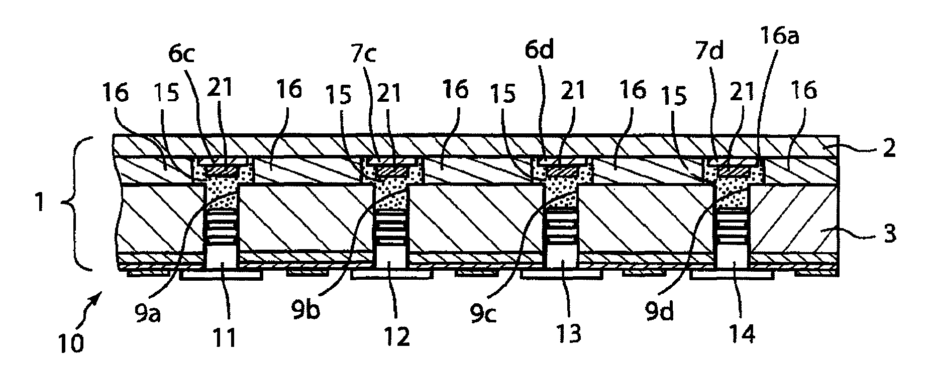
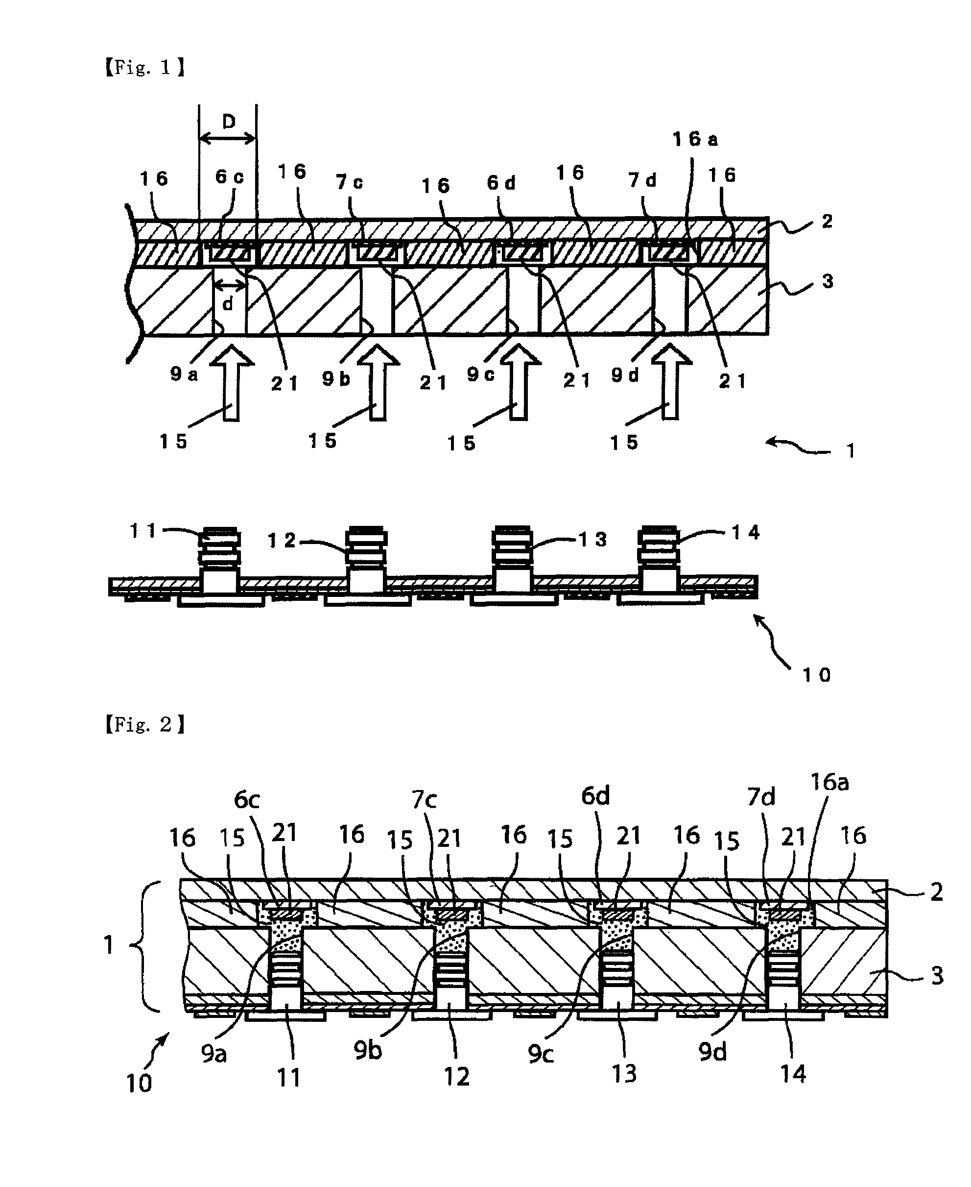
[0049]In this drawing, the touch input function-equipped protection panel 1 includes (a) an upper electrode plate 2a having a flexible transparent insulating film of engineering plastic such as a polycarbonate, polyamide, or polyether ketone, or a film of an acrylic, polyethylene terephthalate, or polybutylene terephthalate and (b) a lower electrode plate 3 made of an inflexible engineering plastic such as a polycarbonate, polyamide, or polyether ketone; a plastic plate of an acrylic, polyethylene terephthalate, or polybutylene terephthalate; or a laminated plate thereof....


PUM

PropertyMeasurementUnit
thicknessaaaaaaaaaa
flexibleaaaaaaaaaa
transparentaaaaaaaaaa

Abstract

A touch input function-equipped protection panel for an electronic device display window which can suppress deterioration of electric properties and appearance quality in a lead wire connection part, includes a touch panel having a flexible upper electrode plate and an inflexible lower electrode plate arranged face-to-face at a prescribed gap in a manner that the electrode surfaces are directed to inside and being formed by sticking the outer circumferential parts of the respective electrode plates with an insulating adhesive layer interposed therebetween; a decorative film having a transparent window part and stuck to the surface of the upper electrode plate; and a pin-equipped lead wire for extracting an electric signal from an electrode terminal of the electrode plate through respective metal pins inserted into a plurality of through holes formed on the lower electrode plate, wherein an elastomeric binder-containing conductive adhesive layer is formed on the electrode terminal of at least one of the upper electrode plate and the lower electrode plate as an underlayer of a conductive adhesive to be injected into the respective through holes.

Description

TECHNICAL FIELD[0001]The present invention relates to a touch input function-equipped protection panel for an electronic device display window capable of suppressing deterioration of electric properties and external appearance quality in a lead wire connection part.BACKGROUND ART[0002]A touch panel is mounted on a display part of mobile electronic terminals such as PDA and handy terminals, OA appliances such as copying machines and facsimiles, smart phones, mobile phones, portable game devices, electric dictionaries, car navigation systems, compact type PC, various kinds of domestic electric articles, and other appliances.[0003]A method for mounting the above touch panel generally involves fitting a display of a LCD or the like in a lower side casing between an upper side casing and the lower side casing to be combined, sticking a touch panel on the display, and thereafter putting the upper side casing having an aperture part corresponding to the display area of the touch panel on t...

Claims


Application Information

Patent Timeline
Patent Type & Authority Patents(United States)
IPC IPC(8): G02F1/1335
CPCG06F3/045H01R4/04H01H2207/014H01H2207/01
Inventor NISHIKAWA, KAZUHIROKAI, YOSHIHIRONAKAMURA, KAZUTO
Owner NISSHA PRINTING COMPANY
Why Eureka
Try Eureka