Drop coating apparatus

a technology of coating apparatus and droplet, which is applied in the direction of inking apparatus, instruments, manufacturing tools, etc., can solve the problems of unsuitable line head system for color filter substrate recovery, increased waste of fluid, and high probability of nozzle clogging, etc., and achieves high efficiency and high efficiency.

Active Publication Date: 2011-12-20
SHARP KK
View PDF17 Cites 9 Cited by
  • Summary
  • Abstract
  • Description
  • Claims
  • Application Information

AI Technical Summary

Benefits of technology

[0014]Accordingly, an object of the present invention is to provide a droplet applying apparatus which is capable of efficiently applying droplets to specified portions (e.g., coloring failure portions) of the substrate and moreover performing alignment of the substrate in short time with high precision.

Problems solved by technology

However, the line head system would be unsuitable for recovery of color filter substrates as shown in, for example, JP 2003-66218 A. JP 2003-66218 A shows a system which includes, as part of the manufacturing method of color filter substrates, ejecting a color filter material only to failure points on occurrence of coloring failure portions in the color filter substrate.
Using the line head system as a means for correcting such failure points scattered on the color filter substrate would involve the same processing time as in the ejection of droplets to all over the substrate, and moreover cause most of the nozzles to be non-operating nozzles that perform almost no ejecting operation, leading to a high likelihood of occurrence of nozzle clogging.
Further, maintenance operation would be required for all the nozzles, leading to increases in unnecessary waste fluids.
Also, with a desire for uniformized ejection quantity, the line head system would give rise to a need for performing ejection quantity correction on a total of thousands of nozzles, one by one, despite the purpose of merely ejecting droplets to scattered desired points, hence extremely inefficient.
Further, in a system in which the ink jet head unit that has been widely used in general-purpose printers is reciprocated in plurality on one identical plane, the scanning distance of the ink jet head units is increased, and the scanning speed is also limitative in terms of stable operation, so that the processing time could not be shortened.
In this case, the mark does not come within the field of view in early alignment, giving rise to a need for repetitively searching the mark, with the result that longer alignment time would be taken in some cases.

Method used


Image

  • Drop coating apparatus
  • Drop coating apparatus
  • Drop coating apparatus

Examples


Embodiment Construction

[0077]Hereinbelow, the present invention will be described in detail by embodiments thereof illustrated in accompanying drawings.

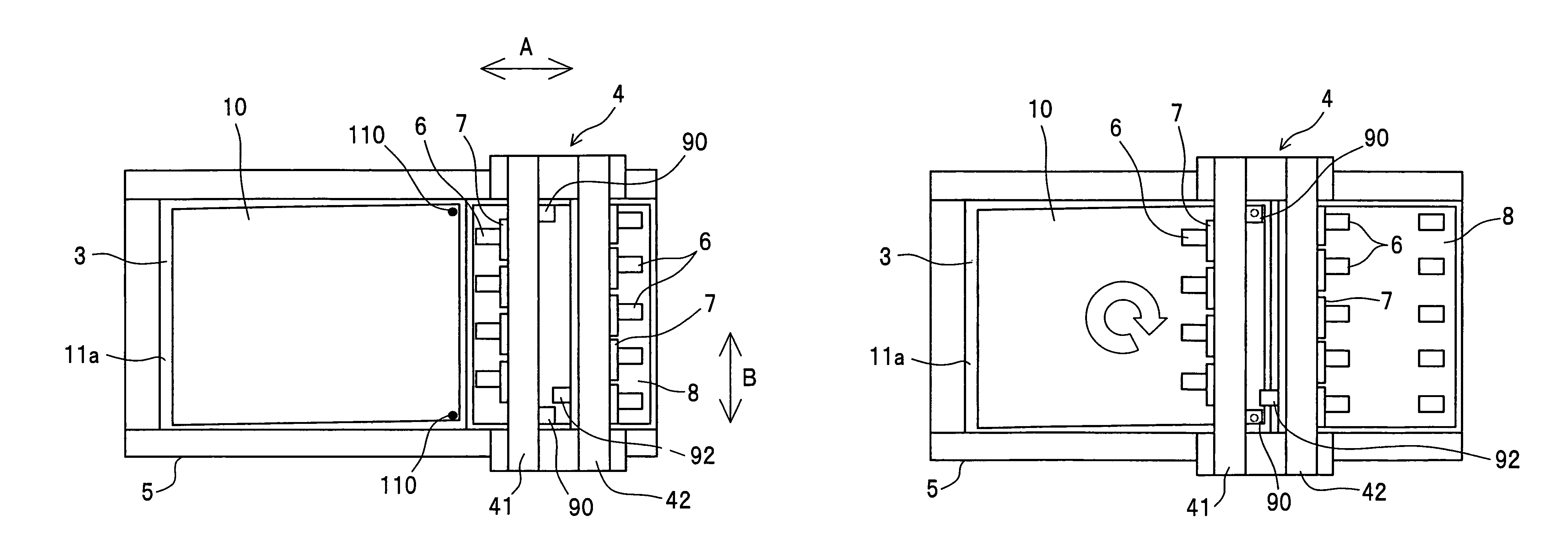
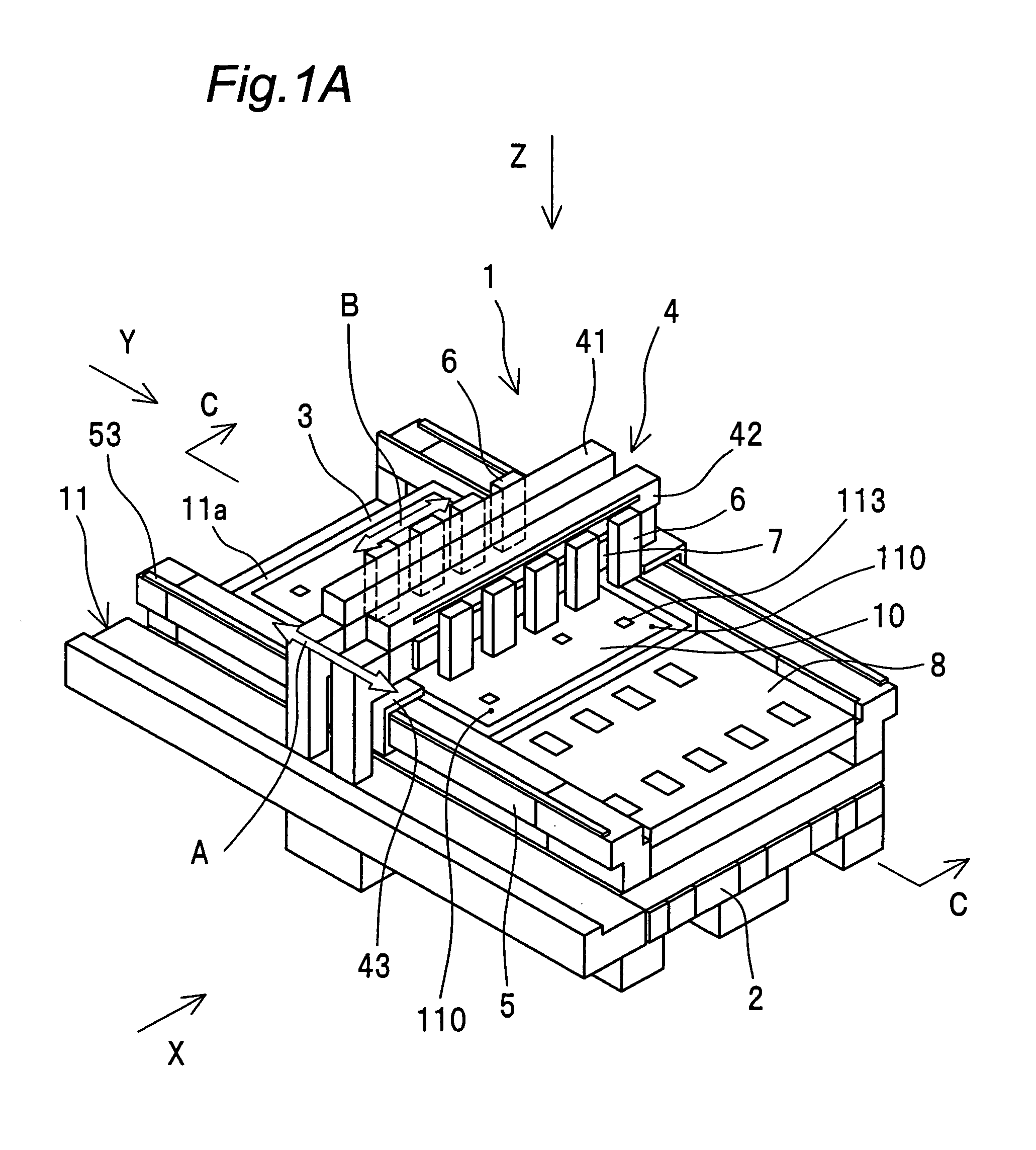
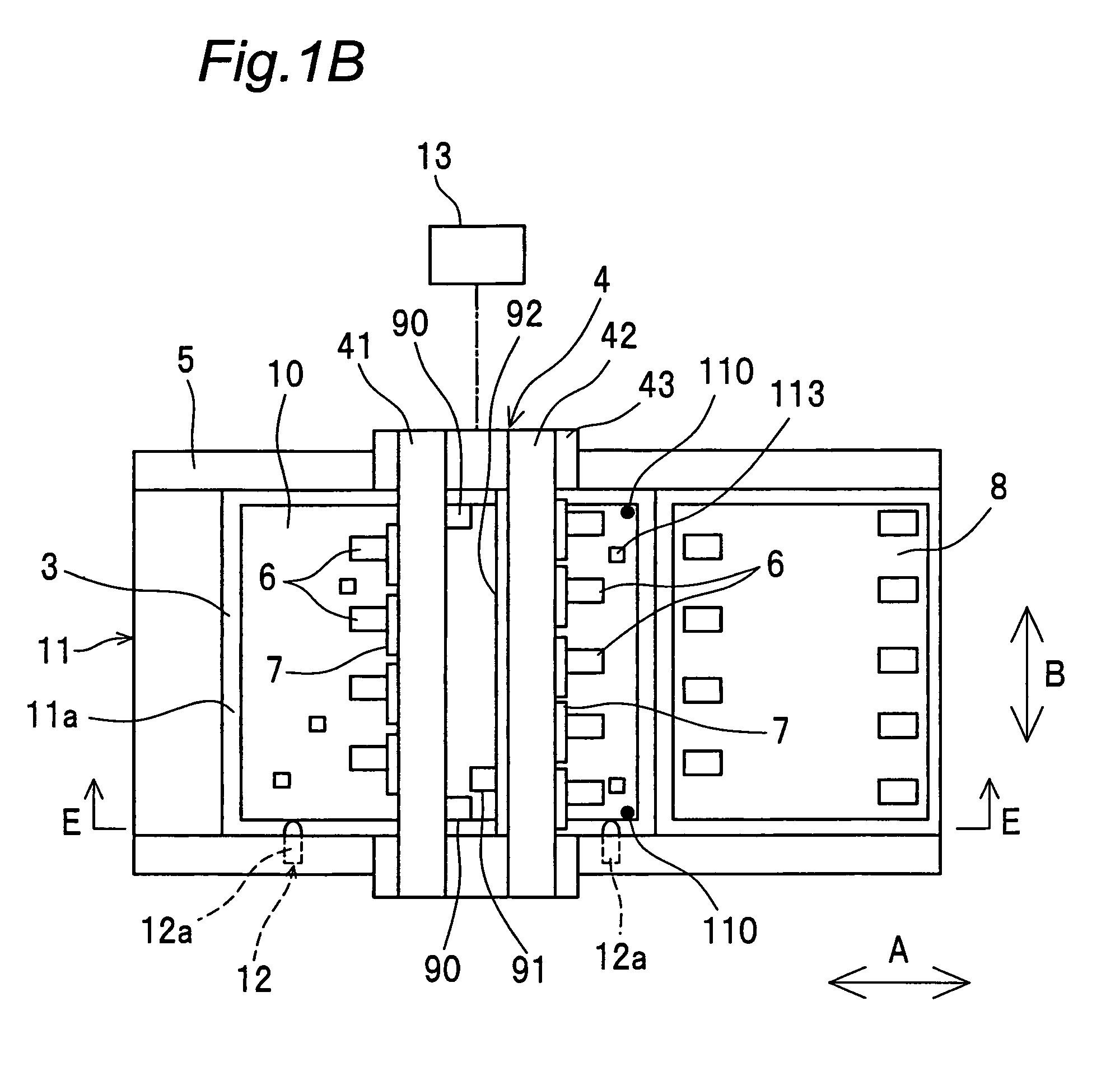
[0078]FIGS. 1A and 1B are constructional views showing an embodiment of a droplet applying apparatus of the invention. The droplet applying apparatus 1 of the invention includes: a base 11 having a mounting surface 11a on which a substrate 10 is to be mounted; an arm part 4 which is fitted to the base 11 so as to be movable relative to the base 11; a plurality of droplet ejecting sections 6 which are fitted to the arm part 4 so as to be movable relative to the base 11 and which eject droplets to the substrate 10 mounted on the mounting surface 11a; image pickup parts 90 for detecting alignment marks 110 of the substrate 10 mounted on the mounting surface 11a; and an attitude adjustment member 12 for adjusting the attitude of the substrate 10 mounted on the mounting surface 11a based on a detection result of the image pickup parts 90.

[0079]The substrate 10 ...


PUM


Abstract

A droplet applying apparatus includes a base 11 having a mounting surface 11a on which a substrate 10 is to be mounted, an arm part 4 which is fitted to the base 11 so as to be movable relative to the base 11 in an arrow A direction, a plurality of droplet ejecting sections 6 which are fitted to the arm part 4 so as to be movable relative to the base 11 in an arrow B direction and which eject droplets to the substrate 10 mounted on the mounting surface 11a, image pickup parts 90 for detecting alignment marks 110 of the substrate 10 mounted on the mounting surface 11a, and a attitude adjustment member 12 for adjusting an attitude of the substrate 10 mounted on the mounting surface 11a based on a detection result of the image pickup parts 90.

Description

TECHNICAL FIELD[0001]The present invention relates to a droplet applying apparatus for applying droplets onto a substrate by an ink jet system or the like.BACKGROUND ART[0002]In recent years, the ink jet technology has been expected for use as manufacturing apparatuses, not merely as printer devices for forming images on paper mediums. For example, in JP 2003-191462 A, an apparatus construction in which droplet ejecting elements using the ink jet system are mounted is disclosed as a manufacturing apparatus for liquid crystal displays, organic EL displays, plasma displays, electron emission elements, electrophoretic display devices and the like. For improvement of landing position precision onto the substrate, in JP 2003-191462 A, a stage for carrying the substrate in one fixed direction with an apparatus base body provided by a granite surface plate, and a carriage mechanism for moving an ink jet head along a direction perpendicular to the stage traveling direction, are provided on ...

Claims


Application Information

Patent Timeline
Patent Type & Authority Patents(United States)
IPC IPC(8): B41J3/00B41J23/00B27B3/04B05B7/00
CPCB41J3/28H01L21/6715B41J2202/09G02B5/201
Inventor NAKAJIMA, YOSHINORITAMURA, TOSHIHIRO
Owner SHARP KK
Why Eureka
Try Eureka