
Tool holder assembly

a tool holder and tool technology, applied in the direction of shaping cutters, manufacturing tools, cutting inserts, etc., can solve the problems of loss of performance, bulky and difficult to use machine tools, and the existing system is more economical, so as to prevent the rollover of the clamping area

Active Publication Date: 2011-12-20
KENNAMETAL INC
View PDF34 Cites 34 Cited by
  • Summary
  • Abstract
  • Description
  • Claims
  • Application Information

AI Technical Summary

Benefits of technology

The solution provides superior support and clamping performance comparable to integral systems, reducing the risk of rollover and maintaining cost benefits by maximizing contact area and directing clamping forces efficiently, thus improving the effectiveness of metal cutting operations in smaller shank holders.

Problems solved by technology

Generally speaking, these existing systems although more economical, suffer loss of performance as compared to their integral shank equivalents because each component must be separately fastened and mated to the tool holder and in a way that optimally supports and clamps the cutting insert.
Existing component style cutoff and grooving systems featuring serrated mating surfaces are adaptations of the above described internal machining tool holders and are bulky and difficult to use on machine tools with turrets that accommodate smaller shank height tooling.
They also require a cylindrical center member for the purpose of component location which adds cost and complexity to the system.

Method used


Image

  • Tool holder assembly
  • Tool holder assembly
  • Tool holder assembly

Examples


Embodiment Construction

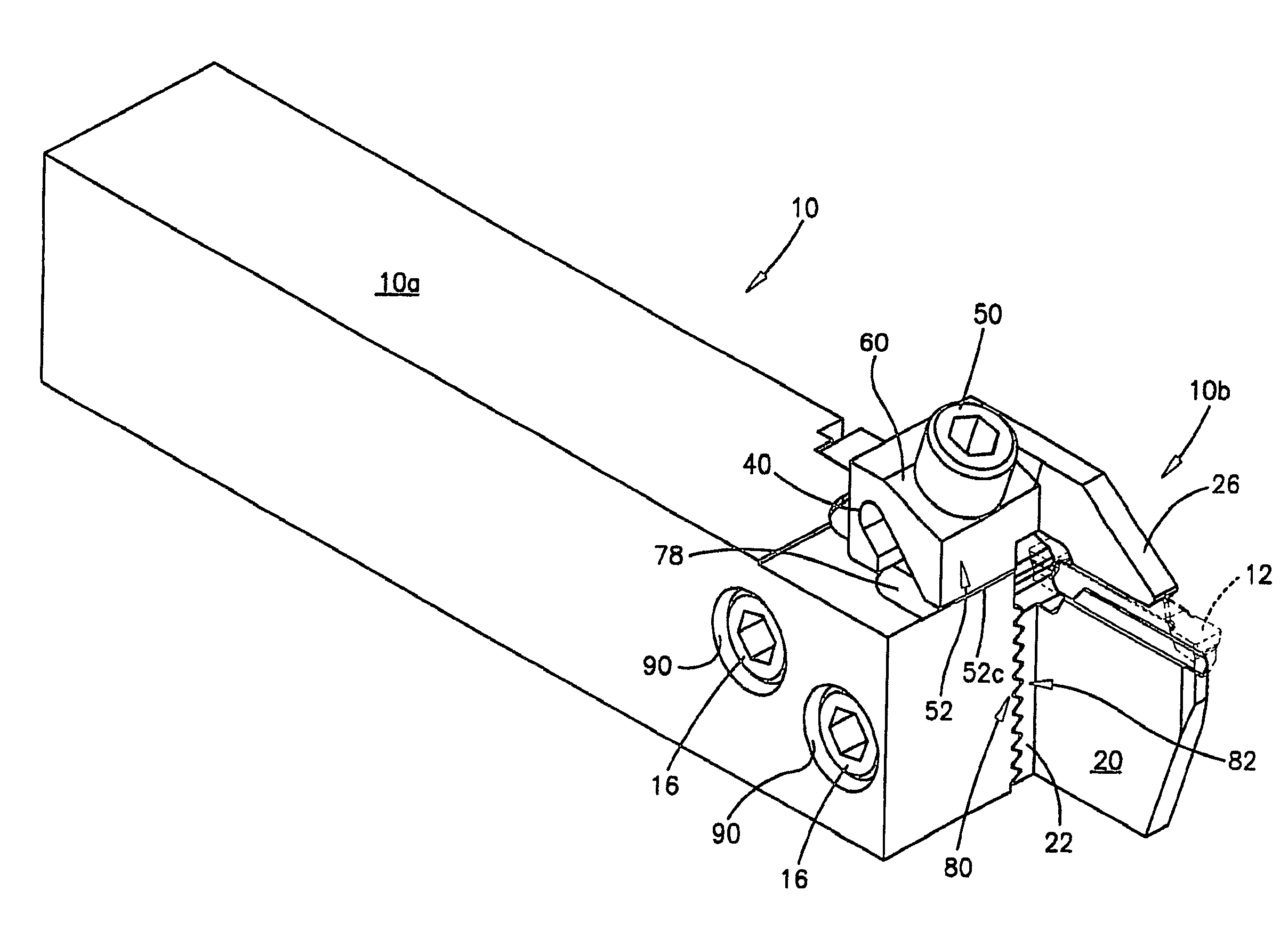
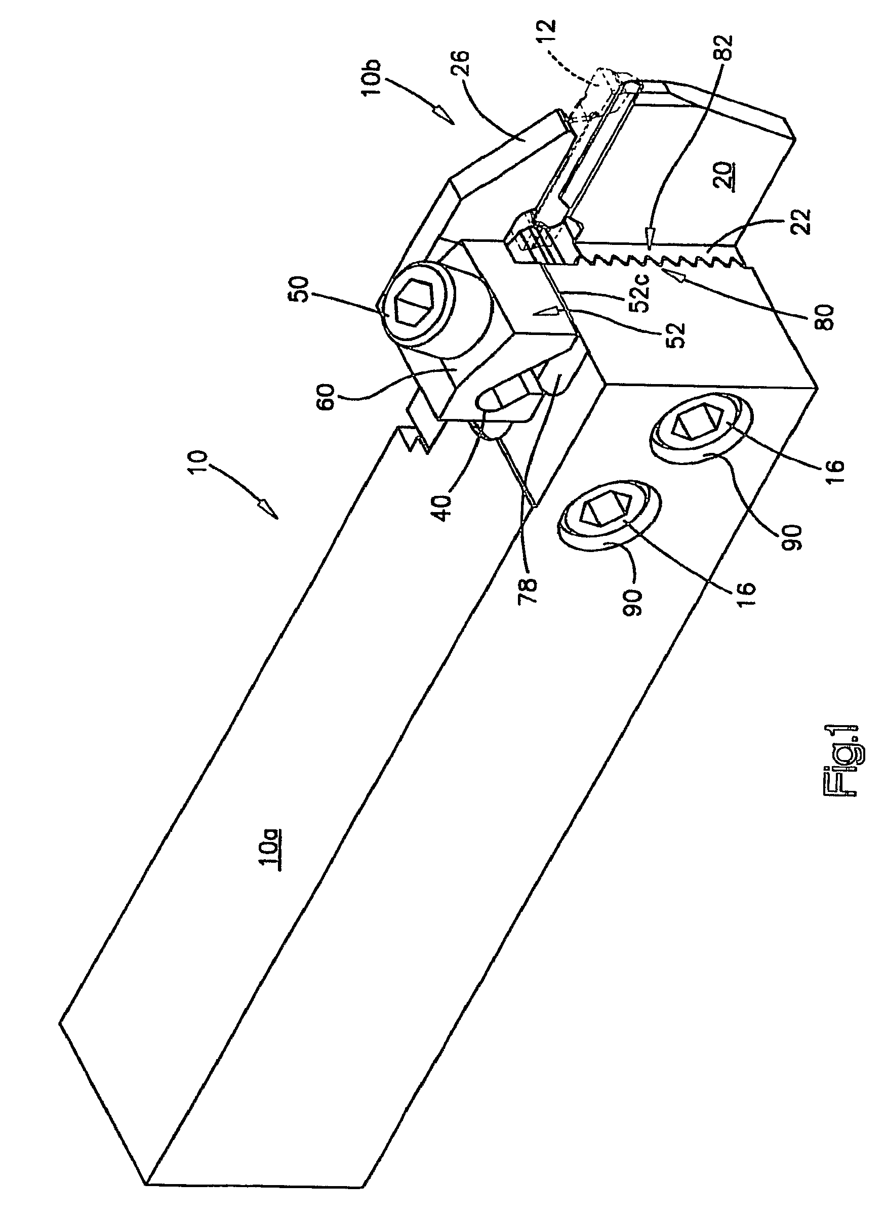
[0022]FIG. 1 illustrates the overall construction of a tool holder assembly 10 constructed in accordance with a preferred embodiment of the invention. The tool holder assembly 10 is used to support a cutting insert 12 in a machining position with respect to a workpiece (not shown). The tool holder assembly includes a bar-like tool holder 10a which is suitably mounted or attached to a machine tool. Typically, the tool holder 10a is secured to a “pocket” of a turret that forms part of the machine tool. This enables the tool holder assembly 10 and hence the associated cutting insert 12 to be moved to various positions in order to perform cutting operations on a rotating workpiece such as bar or tube stock (not shown).

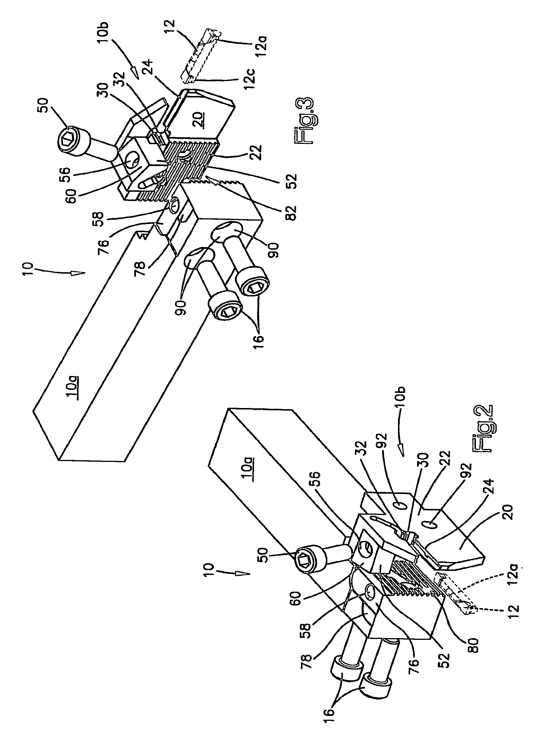
[0023]In accordance with the invention, a cutting insert support / clamp indicated generally by the reference character 10b is removably secured to the tool holder 10a by a pair of socket bolts 16. Referring also to FIGS. 2 and 3, the insert support / clamp 10b is of the blade...


PUM

PropertyMeasurementUnit
anglesaaaaaaaaaa
clamping forcesaaaaaaaaaa
forceaaaaaaaaaa

Abstract

A tool holder assembly that includes a tool holder member adapted to be secured to a machine tool and a cutting insert support / clamp for clamping and supporting a cutting insert. The support / clamp member includes a plurality of serrations that are engageable with complementally formed serrations on the tool holder whereby a tight fitting engagement is achieved using removable fasteners. The support / clamp includes a clamping arm elastically movable towards and away from a support base and a clamping block connected to the connecting arm adapted to receive clamping forces from a threaded clamping bolt. The clamping bolt defines a force applying surface located in a first plane whereas the clamping block defines a force receiving surface located in a second plane, the first and second planes located at a diverging angle with respect to each other. The clamping block includes an edge portion engageable with a step on the tool holder that is spaced from the clamping arm. The diverging planes and the engagement of the clamping block with the stepped portion increases the force applied by the clamping arm to the cutting insert for a given adjustment of the clamping bolt and resists rollover of the insert.

Description

TECHNICAL FIELD[0001]The present invention relates generally to metal cutting apparatus and methods, and in particular to a tool holder assembly for supporting and clamping a cutting insert in a machining position within a machine tool.BACKGROUND ART[0002]Cutoff and grooving systems with replaceable components are known in the art and are used on lathes and other turning equipment. The use of replaceable components reduces the overall cost of a grooving or cutoff system by allowing replacement of less costly support and clamping members rather than the replacement of the entire tool holder. Some existing systems allow the separate replacement of the support member or the clamping member. Other systems combine these two components into one member for inventory simplification.[0003]Generally speaking, these existing systems although more economical, suffer loss of performance as compared to their integral shank equivalents because each component must be separately fastened and mated t...

Claims


Application Information

Patent Timeline
Patent Type & Authority Patents(United States)
IPC IPC(8): B23B27/00B23B27/04
CPCB23B29/043B23B29/046B23B2205/02Y10T407/2286Y10T407/2288Y10T407/2282Y10T407/227B23B2260/132B23B29/04B23B29/12
Inventor NICHOLAS, ROGER
Owner KENNAMETAL INC
Learn More