Bio-implantable ultrasound energy capture and storage assembly including transmitter and receiver cooling

a technology of energy capture and storage assembly and implantable devices, which is applied in the field of bioimplantable energy capture and storage systems, can solve the problems of rechargeable batteries heretofore not finding wide use in implantable medical device applications, and the life of most implantable electro-devices is limited

Active Publication Date: 2011-12-20
PIEZO ENERGY TECH
View PDF50 Cites 103 Cited by
  • Summary
  • Abstract
  • Description
  • Claims
  • Application Information

AI Technical Summary

Benefits of technology

[0010]The present invention overcomes the aforesaid and other deficiencies of the prior art, by providing an apparatus and method which generates acoustic energy, and transmits that acoustic energy wirelessly through skin and tissue to an implanted piezoelectric assembly comprising a piezoelectric element comprising lead-magnesium-niobate in lead-titanate (PMN-PT) that converts the acoustic energy into electrical energy. The technique is called ultrasound electrical recharging (USER). As will be discussed below, using piezo elements formed of PMN-PT provides unique advantages not seen with conventional piezo element formed of PZT. That electric energy can then be used to operate and / or charge or recharge a battery or capacitor to operate a pacemaker, defibrillator, neurostimulators, sensor readouts, or other implanted devices.

Problems solved by technology

The lifetime of most implantable electro-devices is limited by the longevity of the power source.
Moreover, despite advances in battery technology, batteries currently consume 50% or more of the weight and volume of most implanted devices.
Rechargeable batteries heretofore have not found wide use in implantable medical device applications.
Patient compliance and recharge frequency limited the utility of rechargeable batteries.
While this technique can provide considerable power transmission, it has its disadvantages.
The more power required, the larger the coils, leading to a heavy device with a large footprint both inside and outside of the body.
Orientation of the two coils is critical, there is the potential for electromagnetic interference with other devices in the area, and nearby metal can be heated by eddy currents.
Devices such as described above have, in practice, not proved to be satisfactory in that they were extremely limited in the amount of power that could be transmitted through the skin and tissue of the patient without causing excessive heating with the potential for tissue damage and the like, or because their objectives required lower power.
This limitation of the prior art is, in part, a result of the use of PZT-based piezoelectric ceramic materials which are relatively inefficient when it comes to converting energy and transferring the energy through the skin and tissue.

Method used


Image

  • Bio-implantable ultrasound energy capture and storage assembly including transmitter and receiver cooling
  • Bio-implantable ultrasound energy capture and storage assembly including transmitter and receiver cooling
  • Bio-implantable ultrasound energy capture and storage assembly including transmitter and receiver cooling

Examples


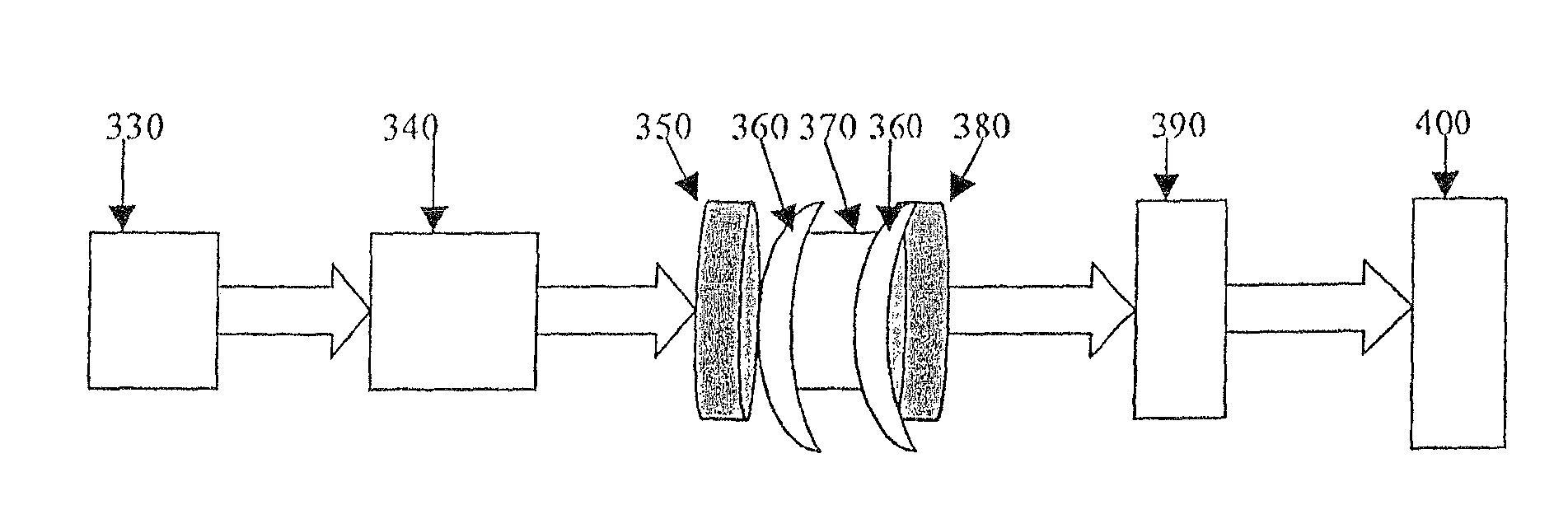
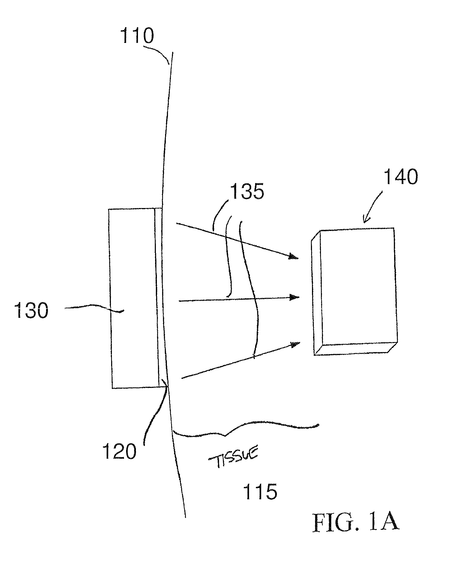
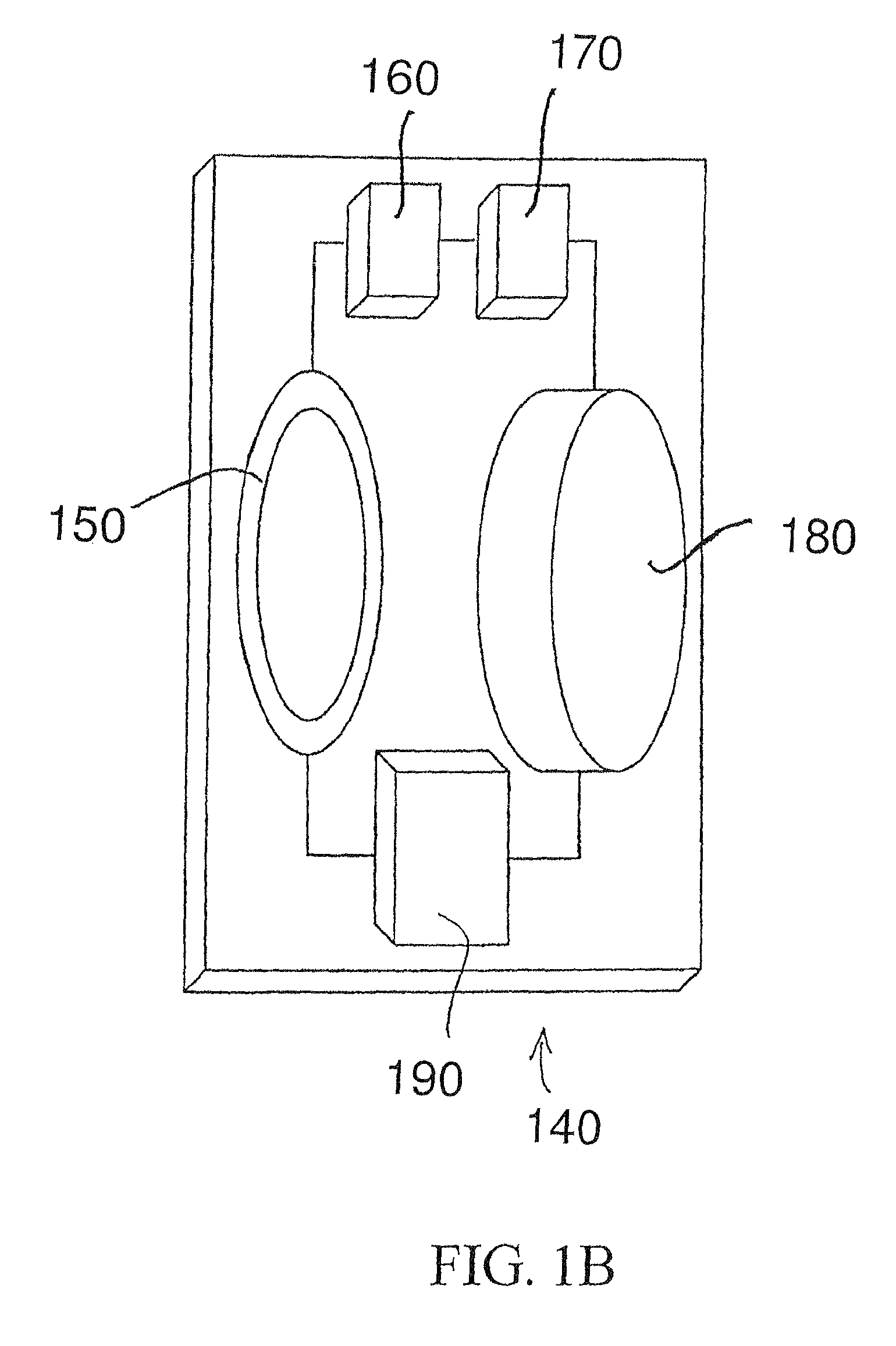
Embodiment Construction

[0022]Reference throughout this specification to “one embodiment,”“an embodiment,” or similar language means that a particular feature, structure, or characteristic described in connection with the embodiment is included in at least one embodiment of the present invention. Thus, appearances of the phrases “in one embodiment,”“in an embodiment,” and similar language throughout this specification may, but do not necessarily, all refer to the same embodiment.

[0023]The described features, structures, or characteristics of the invention may be combined in any suitable manner in one or more embodiments. In the following description, numerous specific details are recited to provide a thorough understanding of embodiments of the invention. However, the invention may be practiced without one or more of the specific details, or with other methods, components, materials, and so forth. In other instances, well-known structures, materials, or operations are not shown or described in detail to av...


PUM


Abstract

A bio-implantable energy capture and storage assembly, including an acoustic energy transmitter for contact with the skin, and an acoustic energy receiver—converter for converting acoustic energy to electrical energy; and a battery or capacitor connected to the energy converter. The acoustic energy receiver/converter is contained within a biocompatible implant.

Description

CROSS REFERENCE TO RELATED APPLICATION[0001]This application is a continuation in-part of my prior U.S. application Ser. No. 12 / 136,743, filed Jun. 10, 2008 now abandoned, which application in turn claims priority from U.S. Provisional Application Ser. No. 60 / 944,325, filed Jun. 15, 2007.STATEMENT REGARDING FEDERALLY SPONSORED RESEARCH OR DEVELOPMENT[0002]This invention was made in part with Government support under grants number 1R43EB007421-01A1 and number R44EB007421 awarded by the National Institutes of Health (NIH). The Government has certain rights in the invention.FIELD OF THE INVENTION[0003]The invention is directed to bio-implantable energy capture and storage systems. The invention has particular utility as an energy capture and storage system designed to harvest acoustic energy transmitted through body tissues, and to convert that acoustic energy into electrical energy, and will be described in connection with each utility, although other utilities are contemplated.BACKGR...

Claims


Application Information

Patent Timeline
Patent Type & Authority Patents(United States)
IPC IPC(8): A61N1/00
CPCA61N1/3787H02J7/025A61M5/14276A61M39/0208A61M2205/04A61M2205/825H02J7/34H02J7/00712H02J50/90H02J2310/23H02J50/15
Inventor RADZIEMSKI, LEON J.
Owner PIEZO ENERGY TECH
Why Eureka
Try Eureka