Missile with system for separating subvehicles

a technology of subvehicle and missile, which is applied in the direction of launching weapons, cosmonautic vehicles, transportation and packaging, etc., can solve the problems of large shock load on the subvehicle, unsatisfactory heaviness, and complex structure of the subvehicle, and achieves the difficulty of integrating with other systems

Active Publication Date: 2011-12-27
RAYTHEON CO
View PDF20 Cites 6 Cited by
  • Summary
  • Abstract
  • Description
  • Claims
  • Application Information

AI Technical Summary

Benefits of technology

[0005]A separation mechanism for separating subvehicles from a spacecraft or missile includes an integrated mechanism for disconnecting, releasing, and ejecting said subvehicles. The unified or integrated mechanism reduces weight and shock loads, relative to prior systems with separate mechanisms for disconnecting electrical, fiber optic, and / or cryo lines, releasing the subsystem, and ejecting it to a desired velocity. Each subvehicle may have a single pyrotechnic device or other gas-generating device that moves a cutter to sever cryogenic lines and mechanical coupling, and also activates a piston to push the subvehicle away from the main missile body. By using a single pyrotechnic device or other gas generating device to separate a subvehicle from the main missile body, as well as sever cryogenic lines coupling the two, shocks on the subvehicle are reduced. This leads to improved performance. In addition, the system may eject a subvehicle in a direction substantially perpendicular to an axis of the subvehicle and / or substantially perpendicular to an axis of the main missile body, leading to an improved spacing of the subvehicles. For example, the subvehicles may be spaced on a wider footprint than for prior systems.
[0014]According to an embodiment of the invention, aspects described above and below may have one or more of the following features: a separation system includes a single pressurized gas source or pyrotechnic gas generator for decoupling and separating all of the subvehicles; alternatively, each of the subvehicles is separated by a different pressure source; a separation system uses a piston, driven by pressurized gas, to push a subvehicle away from a main missile body; the piston moves within a space between a piston cylinder and a piston sleeve; a piston vent is used to communicate pressurized gasses, to move the piston; the piston presses against a fitting on the subvehicle; the actuation of the separation is caused by severing a retention rod with a cutter or actuating a ball lock or segment lock, or releasing any locking system, using the same pressurized gases that move the piston to cause separation; the piston is retained with the missile main body after separation; the piston may have multiple segments, which may initially be stacked or nested within each other, and which may move relative to one another under influence of the pressurized gases, to expand the piston and push away the subvehicle; the subvehicle may have a fitting which fits inside the piston; this fitting may have ramped surfaces on a protruding lip, which urge balls into a piston groove on an inner surface of the piston; a cutter may be driven by pressurized gas to sever a retention rod and / or cryogenic lines; the cutter may have a concave cutting surface; the retention rod may have a notched surface; the notched surface may have a V shape, or a scalloped shape, for example having a semicircular cross-section; a pressurized gas source, such a pyrotechnic device, is detonated, producing pressurized gases that drive a cutter that severs or otherwise disconnects a mechanical coupling (for example including a retention rod) and / or cryogenic lines, the pressurized gases also move a piston to push a subvehicle away from a main missile body, with the piston for example pushing on a piston of the subvehicle; a piston may extend perpendicular to an eject direction, in conjunction with a lever to transfer the piston extension direction to a desired ejection direction (this allows more compact packaging of the piston next to the subvehicle); a passive cryogenic line disconnect (the line simply pulls away from the ejection); an actuated cryogenic line disconnect (by use of a pressure source); a passive connector disconnect for electrical connectors, fiber optic connectors, etc.; an actuated connector disconnect (using pressure source to actuate disconnection).

Problems solved by technology

Shortcomings of these methods have included undesirable heaviness, complexity, and large shock loads to the subvehicles, as well as difficulty in integrating with other systems.

Method used


Image

  • Missile with system for separating subvehicles
  • Missile with system for separating subvehicles
  • Missile with system for separating subvehicles

Examples


Embodiment Construction

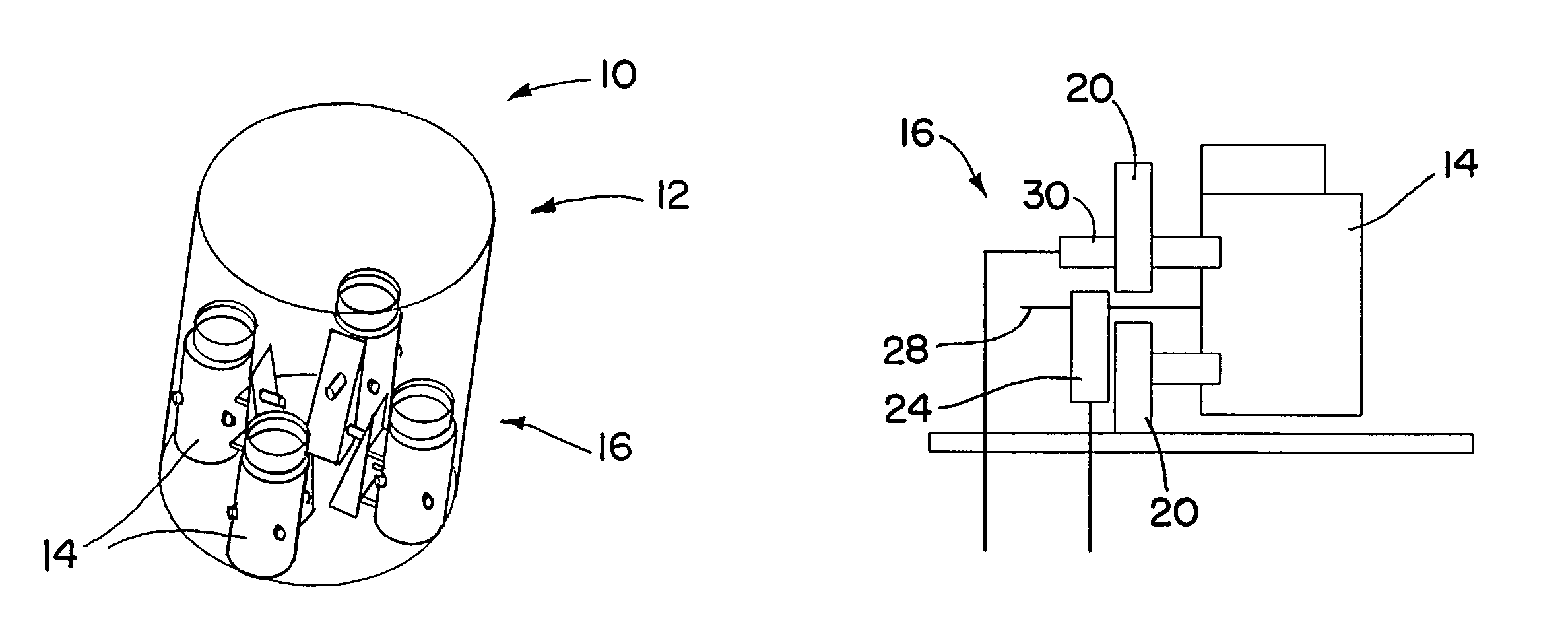
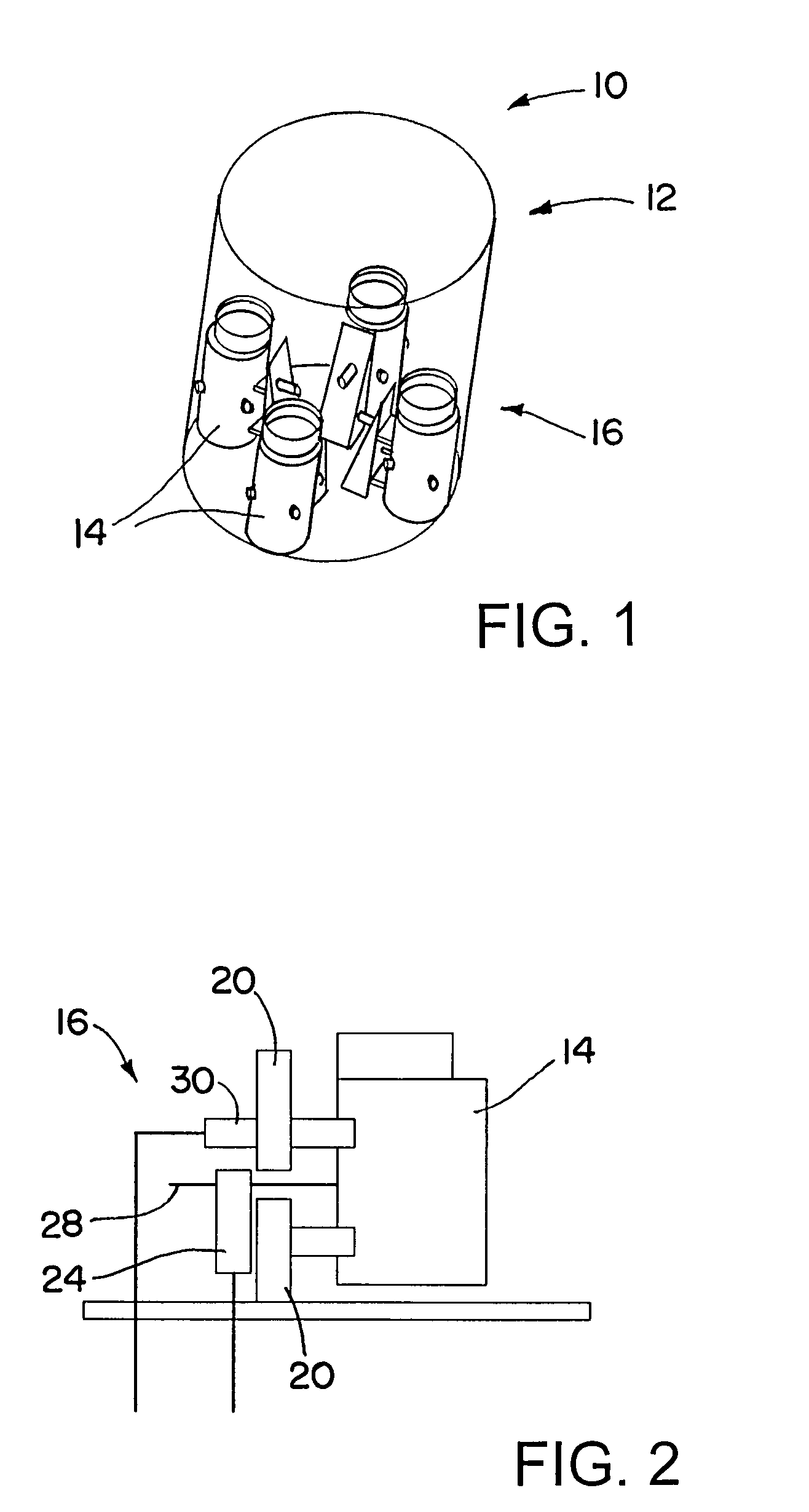
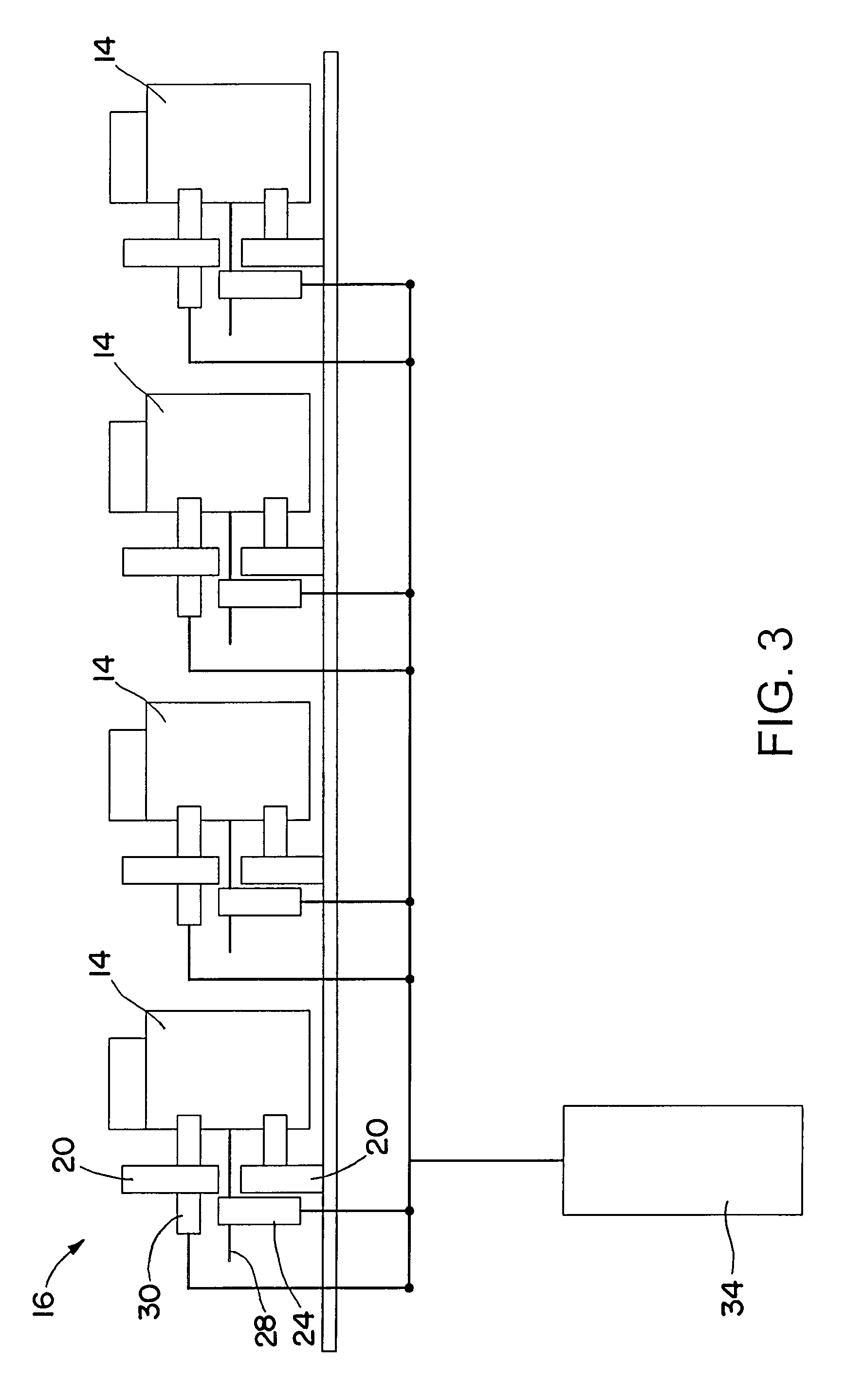
[0038]A missile includes several subvehicles that are initially mechanically coupled to a missile main body, and a separation system for separating the subvehicles from the missile main body. The separation system has a single triggering mechanism to simultaneously provide energy to separate all of the subvehicles. This advantageously provides only a single shock to the system by actuating the system to separate the subvehicles. By limiting the shocks to the single shock of actuating the energy system and the shocks of the mechanical disengagement of the individual subvehicles, the disengagement system has improved performance. The mechanical coupling between the subvehicles and the main body may be provided by retentions rods that are severed during the separation process. The severing of the retention rods may be accomplished at the same time as the severing of cryogenic lines linking the main body and subvehicles. The subvehicles may be separated from the main body in radial dire...


PUM


Abstract

A missile includes several subvehicles that are initially mechanically coupled to a missile main body, and a separation system for separating the subvehicles from the missile main body. The separation system has a single triggering mechanism to simultaneously provide energy to separate all of the subvehicles. This advantageously provides only a single shock to the system by actuating the system to separate the subvehicles. By limiting the shocks to the single shock of actuating the energy system and the shocks of the mechanical disengagement of the individual subvehicles, the disengagement system has improved performance. The subvehicles may be separated from the main body in radial directions substantially perpendicular to a central axis of the main body. This may provide for smoother disengagement, with less tipping, and may provide for greater, more uniform spacing between the disengaged subvehicles.

Description

BACKGROUND OF THE INVENTION[0001]1. Technical Field of the Invention[0002]The invention is in the field of separation systems for separating subvehicles from missiles or spacecraft.[0003]2. Description of the Related Art[0004]Various systems have been used to separate subvehicles from a missile or spacecraft during flight. Among the mechanisms utilized in such systems have been all lock mechanisms, springs, inflatable bladders, severable clamping straps, and rotation of all or parts of the missile or spacecraft. Shortcomings of these methods have included undesirable heaviness, complexity, and large shock loads to the subvehicles, as well as difficulty in integrating with other systems. Therefore it would be advantageous to have improvements in this area.SUMMARY OF THE INVENTION[0005]A separation mechanism for separating subvehicles from a spacecraft or missile includes an integrated mechanism for disconnecting, releasing, and ejecting said subvehicles. The unified or integrated mec...

Claims


Application Information

Patent Timeline
Patent Type & Authority Patents(United States)
IPC IPC(8): F42B12/58
CPCF42B12/60F42B15/36
Inventor HLAVACEK, GREGG J.FLAHART, NIGEL B.ADANG, DAVID A.FACCIANO, ANDREW D.
Owner RAYTHEON CO
Why Eureka
Try Eureka