Ultrasonic probe

a technology of ultrasonic probes and probes, applied in the field of ultrasonic probes, can solve the problems of difficult to obtain precise ultrasound images, likely to become, and likely to create vibrations, and achieve the effect of reducing the displacement of the ultrasonic transducer and obtaining precise ultrasonic images

Active Publication Date: 2011-12-27
KONICA MINOLTA INC
View PDF23 Cites 10 Cited by
  • Summary
  • Abstract
  • Description
  • Claims
  • Application Information

AI Technical Summary

Benefits of technology

[0007]It is an object of the present invention to provide an ultrasonic probe that allows precise ultrasonic images to be obtained by swinging an ultrasonic transducer smoothly and reducing displacement of the ultrasonic transducer.

Problems solved by technology

Therefore, vibrations are likely to be created by contact between gear structures when the swing mechanism is driven.
Such vibrations pose a problem of preventing smooth swing movement of the ultrasonic transducer, i.e., smooth ultrasonic scanning, which results in difficulty in obtaining precise ultrasound images.
Accordingly, the wire is likely to become loose, resulting in displacement of the driven pulley, and furthermore displacement of the ultrasonic transducer connected to the driven pulley.
Such displacement also makes it difficult to obtain precise ultrasonic images.

Method used


Image

  • Ultrasonic probe
  • Ultrasonic probe
  • Ultrasonic probe

Examples


Embodiment Construction

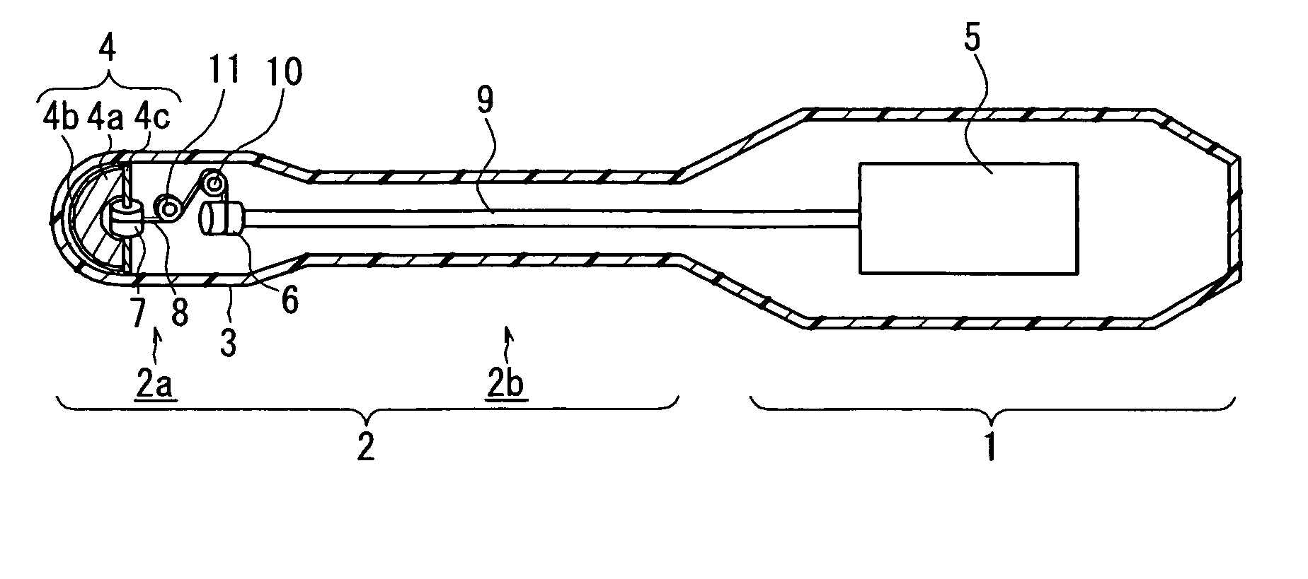
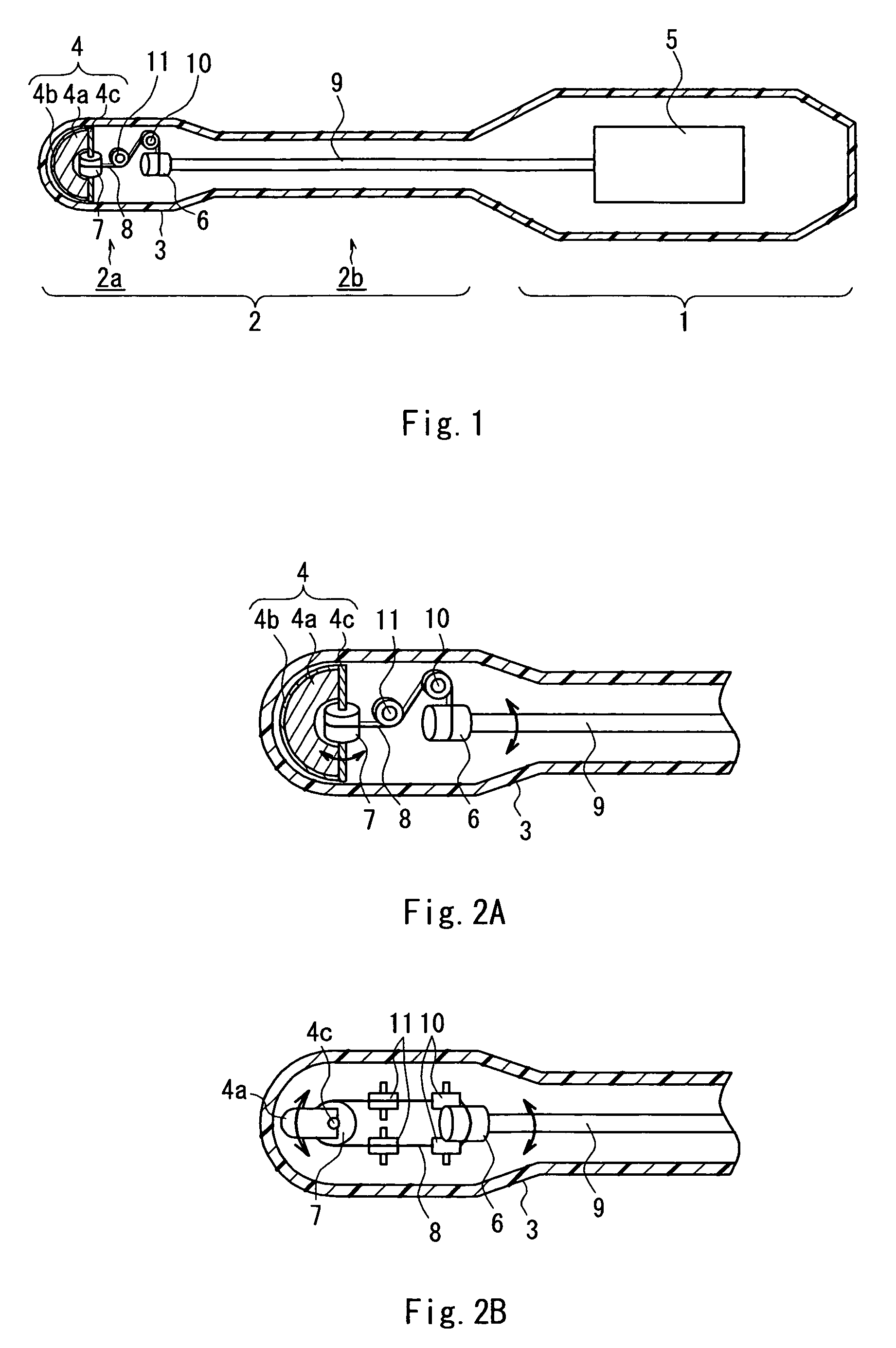
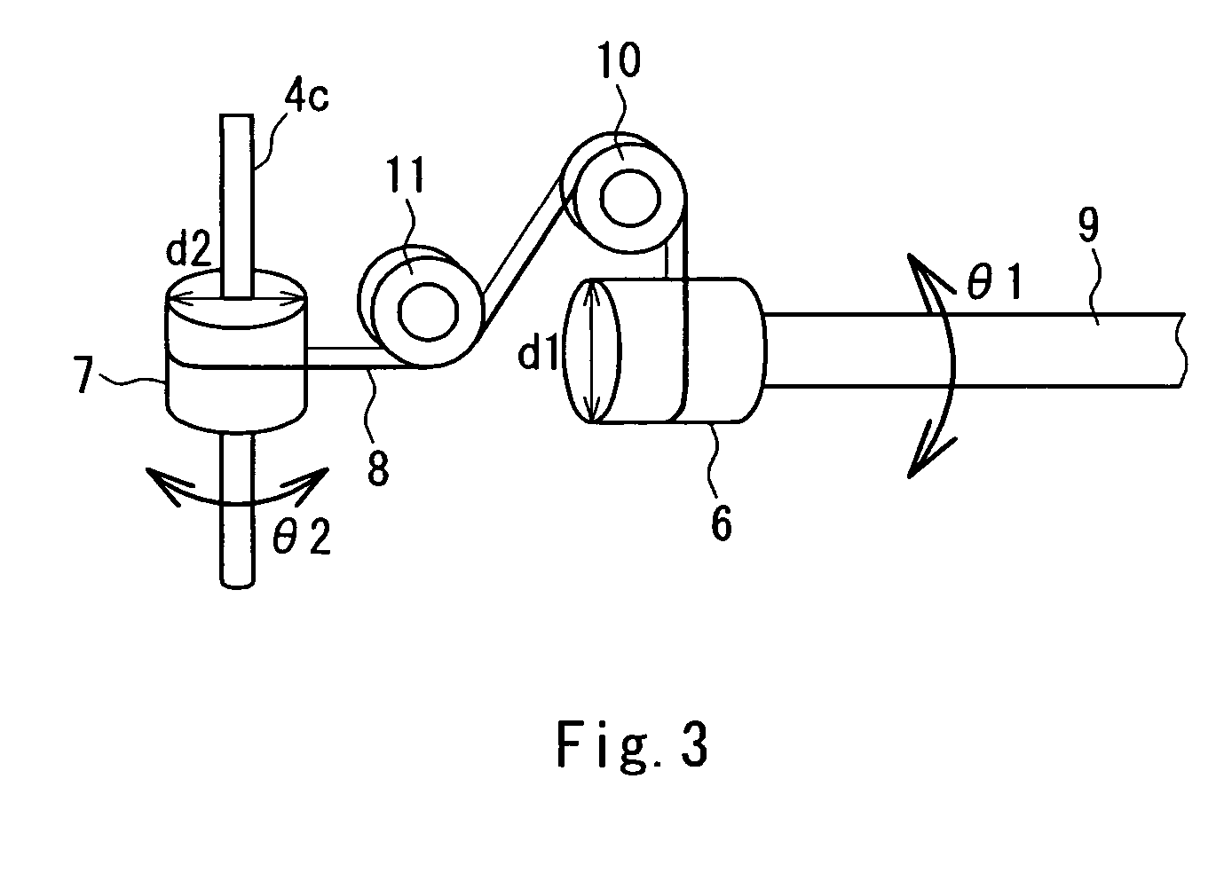
[0017]In an ultrasonic probe of the present invention, a driving force generated by a motor in a grip portion is transmitted to a first pulley via a shaft so as to rotate the first pulley, and the rotational movement of the first pulley is transmitted to a second pulley via a wire so as to rotate the second pulley, whereby a transducer unit can be swung. In this manner, the transducer unit is swung by wire drive without the use of a gear, which makes it possible to reduce undesirable vibrations created when a swing mechanism is driven.

[0018]Further, the driving force of the motor is transmitted to the swing mechanism in an inserting portion via the shaft and in the swing mechanism, transmitted to the transducer unit by the wire. Therefore, the wire can be made relatively short, which makes it possible to reduce loosening of the wire and thus to reduce displacement of the transducer unit.

[0019]In the ultrasonic probe, it is preferable that the first pulley and the second pulley have ...


PUM


Abstract

An ultrasonic probe according to the present invention includes an inserting portion to be inserted into a body cavity and a grip portion 1 held by an operator outside of the body cavity. The inserting portion 2 includes a transducer unit 4, a rotation axis provided in the transducer unit 4, and a swing mechanism for swinging the transducer unit 4 around the rotation axis as a center, and the grip portion 1 includes a motor 5 for generating a driving force for driving the swing mechanism. The swing mechanism includes a shaft 9 connected to the motor 5, a first pulley 6 attached coaxially to the shaft 9, a second pulley 7 attached coaxially to the rotation axis of the transducer unit 4, and a wire 8 connecting the first pulley 6 and the second pulley 7.

Description

TECHNICAL FIELD[0001]The present invention relates to an ultrasonic probe for transmitting and receiving ultrasonic waves to and from a living body by an ultrasonic transducer inserted into a body cavity.BACKGROUND ART[0002]As a probe configuring an ultrasonic diagnostic apparatus for use in the field of medicine, an intracorporeal insertion type ultrasonic probe for carrying out ultrasonic scanning in a body by inserting an ultrasonic transducer into the body cavity of a subject is known.[0003]FIG. 5 is a schematic cross-sectional view showing a structure of a conventional intracorporeal insertion type ultrasonic probe (hereinafter, referred to as a “first conventional example”). An ultrasonic probe having such a structure is described in JP 2001-327501 A, for example. This probe includes an inserting portion 102 to be inserted into a body cavity and a grip portion 101 held by an operator outside of the body cavity. The inserting portion 102 has an elongate rod shape and includes a...

Claims


Application Information

Patent Timeline
Patent Type & Authority Patents(United States)
IPC IPC(8): A61B8/14A61B8/12
CPCA61B8/12A61B8/4461A61B8/445A61B8/4209
Inventor KADOKURA, MASAHIKO
Owner KONICA MINOLTA INC
Why Eureka
Try Eureka