Coolant dosing device

a cooling device and cooling technology, applied in packaging, medical science, surgical instruments for cooling, etc., can solve the problems of extreme wear of sealing means in the region of connecting zone, increased negative impact of metal abrasion shavings on existing filters, and only possible use of them

Active Publication Date: 2011-12-27
CRYOCONCEPTS
View PDF4 Cites 20 Cited by
  • Summary
  • Abstract
  • Description
  • Claims
  • Application Information

AI Technical Summary

Benefits of technology

[0009]It is an object of the invention to provide a coolant dosing device which does not suffer from the aforesaid drawbacks, which functions reliably and is of simple construction.
[0012]Moreover, the high risk of premature unscrewing of the pressure capsule and concomitant high-pressure emission of the gas are prevented, since the built-in valve in the capsule remains closed during unscrewing of the coolant dosing device with no gas being able to escape.
[0015]It is particularly advantageous that the filter has a port size of 5 μl, so that the emanating gas is practically germ-free.
[0017]Due to the structurally simple design of the coolant dosing device and the possibility of its cleaning (simple blowing through the mobile capillary tube when dispenser is unscrewed) with cryogenic gas from the connected capsule, this device has an incomparably long serviceable life.
[0020]It is furthermore advantageous that in a simple manner, by means of screw-like threads, dispensers of any type may be connected by hand to the coolant dosing device, at the point of the gas discharge, and that these dispensers are reliably sealed on the high-polished capillary tube by an O-ring.

Problems solved by technology

However, the disadvantage of these dosing devices resides in the fact that their use is only possible in conjunction with commercially available capsules, because the gas inside the capsules contains, in part, substantial dirt particles.
This causes the formation of metal abrasion shavings having an increased negative impact on the existing filter.
The sealing means in the region of the connecting zone are subject to extreme wear, since the capsule neck with its partially very rough surface properties is poorly suited for sealing.
For physical and technical reasons the built-in filter in the coolant dosing device only offers a very small, effective filter surface.
The coolant dosing device is consequently rendered useless, because micro-sized ice crystal particles, which are formed as a result of the Joule Thomson effect, clog the dispenser capillaries.
Finally, when discharging the amount of residual gas, still present for technical reasons, in a gaseous state at the relatively high discharge velocity of the gas, additional, detaching dirt particles from the interior of the capsule impact negatively on the filter.

Method used


Image

  • Coolant dosing device
  • Coolant dosing device
  • Coolant dosing device

Examples


Embodiment Construction

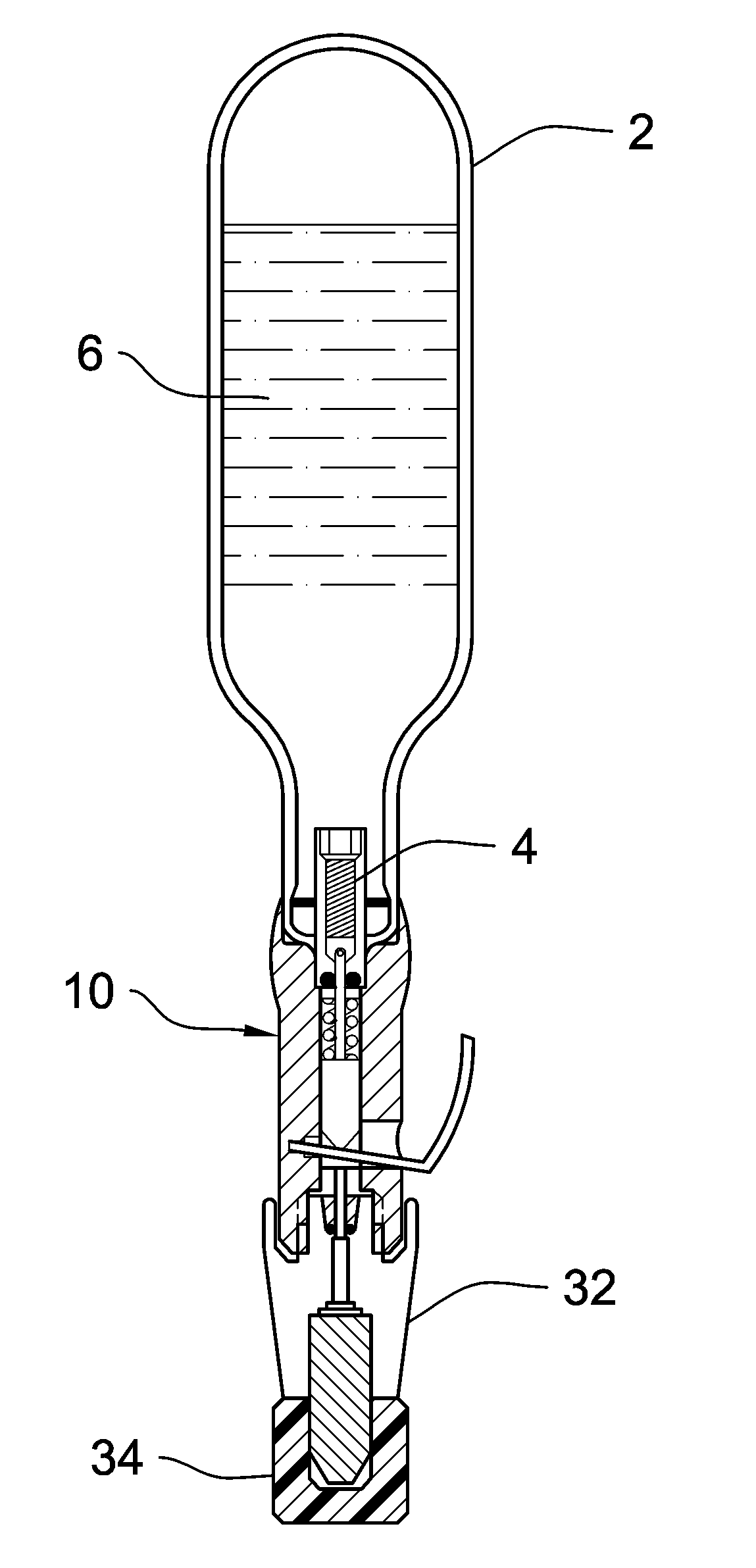
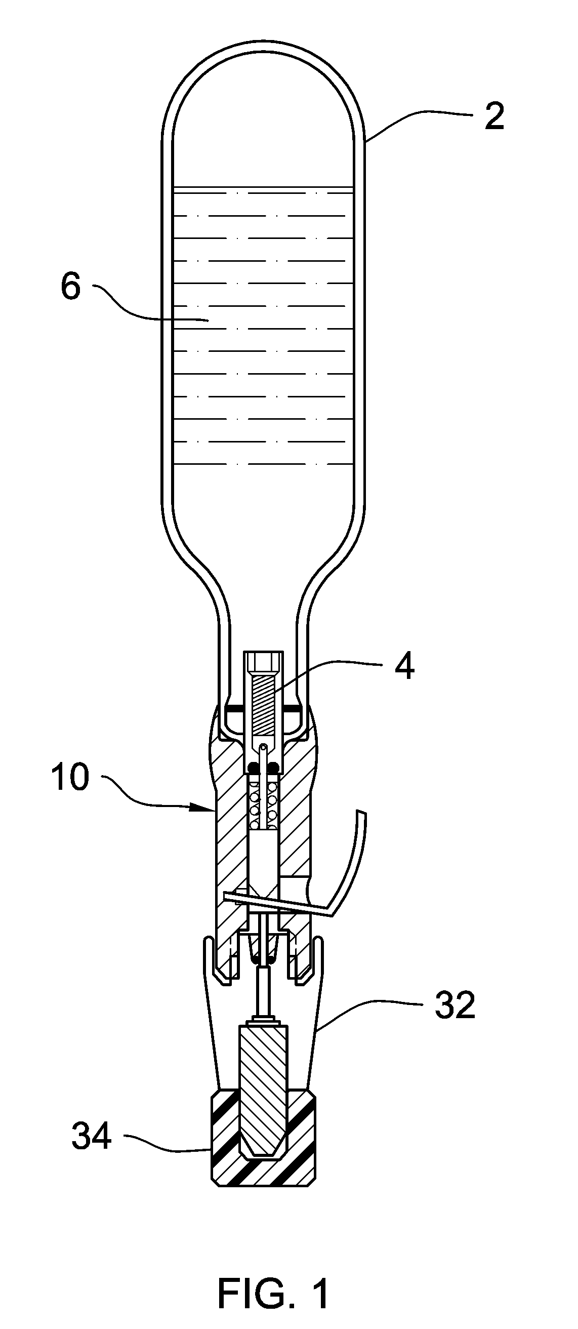
[0025]Referring now to the drawings and particularly to FIGS. 1 and 2, a preferred embodiment of the coolant dosing device of the present invention is shown. The accompanying FIG. 1 shows a coolant dosing device 10 according to the invention with a lever and its connecting component, a capsule with a valve 2 and filter 4, as well as a dosing device 32 with a glass capillary tube nozzle and protective cover 34, shown in sectional view.

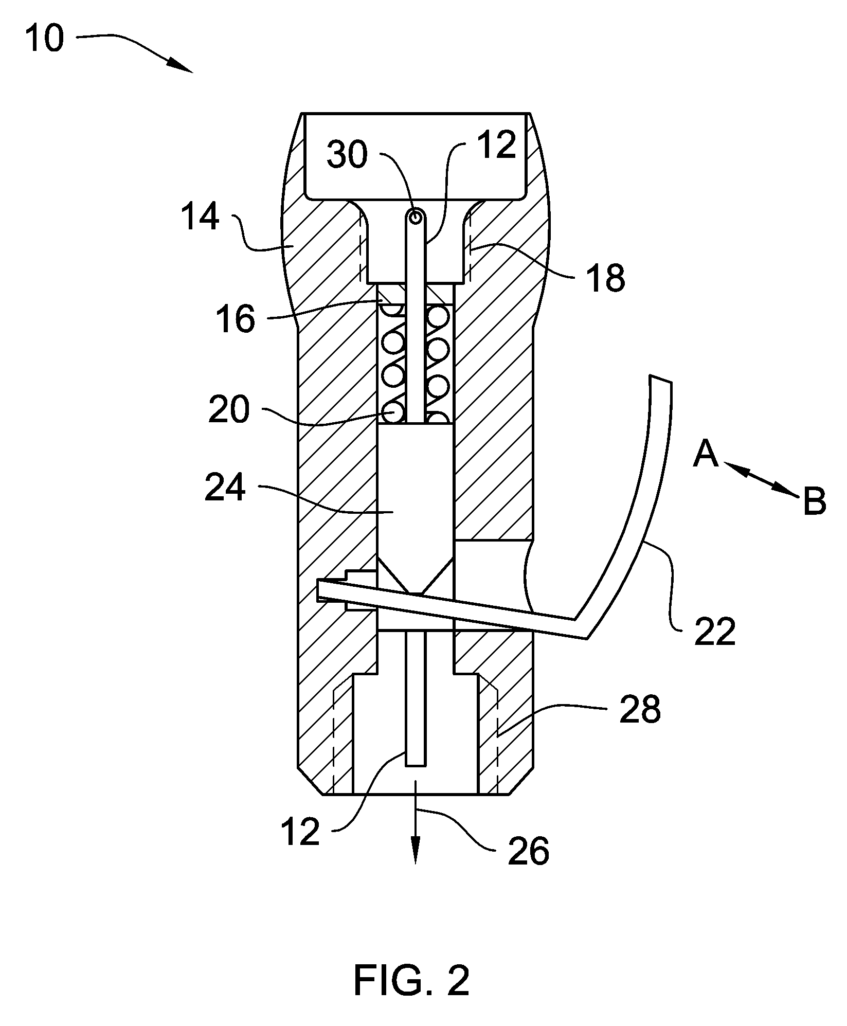
[0026]The accompanying FIG. 2 shows the coolant dosing device 10 on a larger scale in sectional view. The coolant dosing device comprises a capillary tube 12, which on its closed side, in the direction of the capsule, has a port serving as the gas inlet 30.

[0027]With the movement AB of the lever 22, the slide 24, to which force is applied by the spring 20 and which is rigidly connected to the capillary tube 12, by way of a clamp ring 16, is moved in axial direction. As a result of this movement, after connection to the capsule with the valve of the capi...


PUM


Abstract

The invention relates to a coolant dosing device for the application of cryogenic gas for producing low temperatures as required e.g. in cryosurgery. The invention aims to ensure a disturbance-free operation in spite of often dirty gas and to exclude possible operating errors in the connection of capsules of the prior art. According to the invention, the coolant dosing device comprises a capillary tube that receives gas that has been filtered in the capsule and directly supplies it to the dispenser, thereby ensuring a disturbance-free operation. The low force connection between the capsule and the metering device by means of O-rings that are slipped over ensures a tight seal and an error-free operation.

Description

CROSS-REFERENCE TO RELATED APPLICATIONS[0001]This application is an U.S. national phase application under 35 U.S.C. §371 based upon co-pending International Application No. PCT / IB2004 / 002127 filed on Jun. 27, 2004. Additionally, this U.S. national phase application claims the benefit of priority of co-pending International Application No. PCT / IB2004 / 002127 filed on Jun. 27, 2004. The entire disclosures of the prior applications are incorporated herein by reference. The international application was published on Feb. 2, 2006 under Publication No. WO2006 / 010971 A1.BACKGROUND OF THE INVENTION[0002]1. Field of the Invention[0003]The invention relates to a coolant dosing device of the liquid freezing system for cryogenic liquefied gas for producing low temperatures, for example in cryo-medicine.[0004]2. Description of the Prior Art[0005]Coolant dosing devices comprising a liquid freezing system are advantageous, because, during use, the gas consumption comes very close to the coolant dem...

Claims


Application Information

Patent Timeline
Patent Type & Authority Patents(United States)
IPC IPC(8): A61B18/02B67D7/16B67D7/58
CPCA61B18/0218
Inventor STEINFATT, DIETERSTEINFATT, HELGA
Owner CRYOCONCEPTS
Why Eureka
Try Eureka