Flame rod drive signal generator and system

a technology of drive signal and generator, which is applied in the direction of fire alarm, combustion regulation, instruments, etc., can solve the problems of adding significant cost to the control system, system may only have a relatively low voltage, etc., and achieve the effect of facilitating understanding

Active Publication Date: 2011-12-27
ADEMCO INC
View PDF107 Cites 20 Cited by
  • Summary
  • Abstract
  • Description
  • Claims
  • Application Information

AI Technical Summary

Problems solved by technology

However, in many cases, the control system may only have a relatively low voltage power source available, such as 24 Volts, 5 Volts or the like.
However, this method can add significant cost to the control system.

Method used


Image

  • Flame rod drive signal generator and system
  • Flame rod drive signal generator and system
  • Flame rod drive signal generator and system

Examples


Embodiment Construction

[0015]The following description should be read with reference to the drawings wherein like reference numerals indicate like elements throughout the several views. The detailed description and drawings show several embodiments, which are meant to be illustrative of the claimed invention.

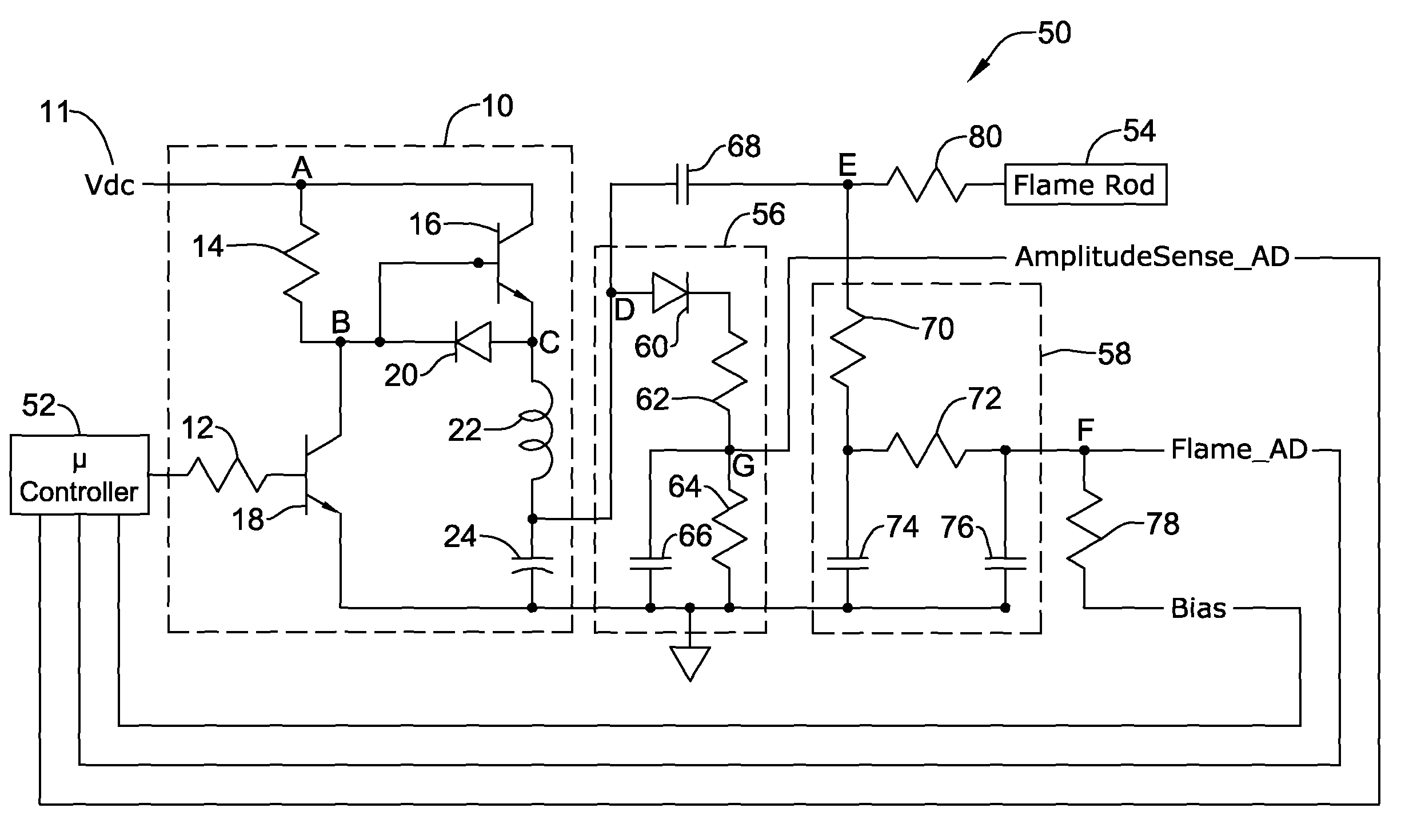
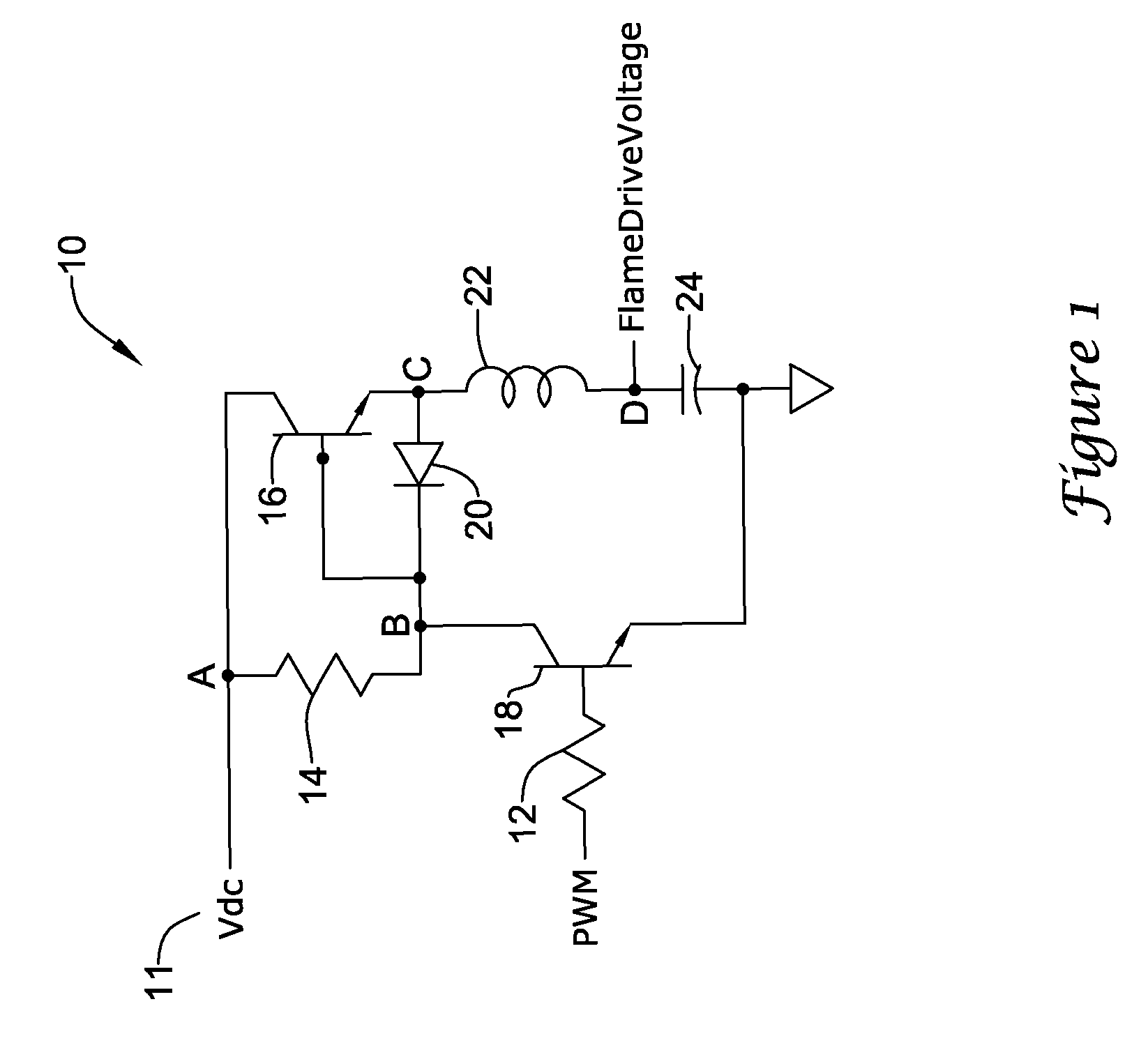
[0016]FIG. 1 is a schematic diagram of an illustrative flame rod drive signal circuit 10 for a combustion system. In the illustrative embodiment, the flame rod drive signal circuit 10 includes a push-pull drive stage and an oscillation network. The push-pull drive stage may have an input and an output. The input of the push-pull drive stage may be connected to a voltage source 11, shown as Vdc, having a first voltage such as 24V, 5V or some other suitable voltage. The oscillation network may include an input and an output. The input of the oscillation network may be connected to the output of the push-pull drive stage and the output of the oscillation network may provide a flame rod drive signal, show...


PUM


Abstract

A flame rod drive signal generator and system for producing a flame rod drive signal for a flame rod of a combustion system. In one illustrative embodiment, the flame rod drive signal generator may include a voltage source, an input signal having a frequency, an LC oscillator and a drive mechanism. The drive mechanism may be powered by the voltage source, and may have an output coupled to the LC oscillator. The drive mechanism may receive the input signal, and produces a current in the LC oscillator that has a frequency that is related to the frequency of the input signal. The LC oscillator may then provide a flame rod drive signal to a flame rod that has an amplitude that is larger than the amplitude of the voltage source. In some cases, a controller may monitor the amplitude of the flame rod drive signal and adjust the frequency, duty cycle, or both, of the input signal to achieve a desired amplitude of the flame rod drive signal. Alternatively, or in addition, the controller may monitor an ionization current produced by the flame rod when the flame rod is subject to a flame.

Description

FIELD[0001]The present invention relates generally to flame sensing circuits, and more particularly, to flame rod drive signal generators and systems.BACKGROUND[0002]Commercial and residential buildings and structures can include many building system components. In some cases, the building components may be gas-fired building components such as furnaces, boilers, water heaters, deep fryers, as well as many other types of gas-fired building components. Gas-fired building components often include a combustion system acting as the heating system for the component. One example combustion system may include a gas source, a gas valve to regulate the gas source, a burner, an ignition system to ignite the burner when desired, and a controller to control the operation of the combustion system.[0003]In some combustion systems, a flame rod may be provided to sense the presence of the flame, indicating that the gas burner is ignited. In this case, the presence of the flame may be detected by an...

Claims


Application Information

Patent Timeline
Patent Type & Authority Patents(United States)
IPC IPC(8): F23Q3/00
CPCF23N5/123
Inventor CHIAN, BRENT
Owner ADEMCO INC
Why Eureka
Try Eureka